
Method and apparatus for removal of microscopic contaminant particulates from superconducting radio frequency cavities and cavity strings

a superconducting radiofrequency and cavity string technology, applied in the direction of cleaning process and apparatus, cleaning liquids, accelerators, etc., can solve the problems of limited particle size, high cost, and limited space, and achieve the effect of reducing activated radioactivity, reducing field emission, and increasing the usable accelerating gradient of cavities

Pending Publication Date: 2021-10-14
JEFFERSON SCI ASSOCS LLC
View PDF0 Cites 0 Cited by
  • Summary
  • Abstract
  • Description
  • Claims
  • Application Information

AI Technical Summary

Benefits of technology

The present invention provides a method and apparatus for cleaning superconducting radio frequency (SRF) cavities and cavity strings during production and in-situ cleaning of contaminated cryomodules after accelerator operation. The cleaning process reduces field emission, improves accelerator capability, increases accelerator availability, better operation efficiency, and reduces activation of accelerator components, emitting less radioactive burden to the environment. The method suppresses field emission and reduces activated radioactivity in accelerator components around cavities. The technical effects of the invention are rapid recovery of contaminated cavities without the need for disassembly and reassembly of the cryomodule, reducing cost and downtime.

Problems solved by technology

Although various cleaning methods have been proposed for final cleaning of cavity strings during production of new cryomodules and for in-situ cleaning of contaminated cryomodules after accelerator operation, they are limited in the size of particles that can be removed and typically require the disassembly and reassembly of the cryomodule, which is extremely time-consuming and expensive.

Method used


Image

  • Method and apparatus for removal of microscopic contaminant particulates from superconducting radio frequency cavities and cavity strings
  • Method and apparatus for removal of microscopic contaminant particulates from superconducting radio frequency cavities and cavity strings
  • Method and apparatus for removal of microscopic contaminant particulates from superconducting radio frequency cavities and cavity strings

Examples


Embodiment Construction

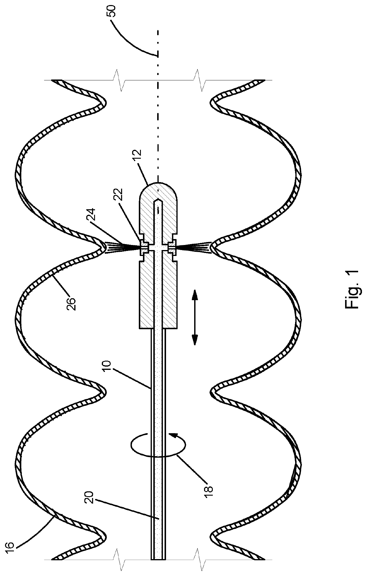
[0019]With reference to FIG. 1, a lance 10 carrying a cleaning head 12 at its end penetrates into the inner space of a superconducting radio frequency cavity 14 or a string 16 of multiple cavities. The orientation of the cavity or the cavity string is either vertical or horizontal depending on the application. The lance rotates 18 as it penetrates progressively over the length of the device under this cleaning treatment. Filtered high pressure, 500-6000 PSI, liquid nitrogen 20 is supplied to the lance 10 by an external cryogenic booster pump, which draws liquid nitrogen from an ordinary external liquid nitrogen storage tank (see FIG. 6). The high pressure liquid nitrogen 20 is transferred by the lance 10 to its cleaning head 12 and exits through a number of nozzles 22, producing high pressure liquid nitrogen jets 24.

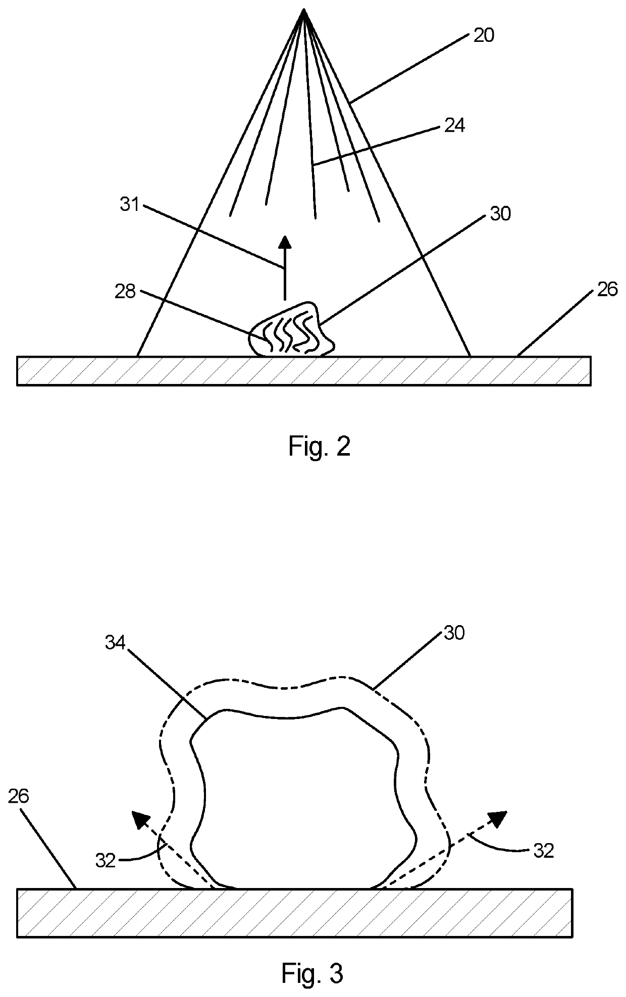
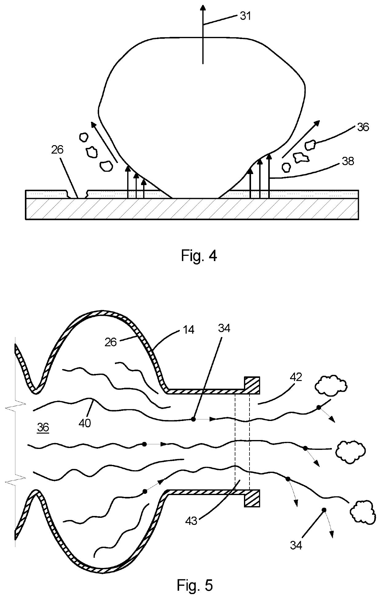
[0020]As shown in FIG. 2, the jets 24, when hitting the cavity wall inner surface 26, transfer energy via sound waves 28 to the cleaning location, hence dislodging micro...


PUM


Abstract

A method and apparatus for removing microscopic contaminant particulates by high pressure liquid nitrogen jet cleaning from the inner surface of a superconducting radio frequency cavity or a string of multiple cavities and transporting the removed particulates out of the inner space enclosed by the cleaned surfaces. The cleaning method of the invention suppresses field emission, resulting in an increase of the usable accelerating gradient of the cavities and a reduction of the activated radioactivity in accelerator components around cavities.

Description

[0001]This application claims the priority of Provisional U.S. Patent Application Ser. No. 62 / 989,627 filed Mar. 14, 2020, the contents of which are incorporated herein by reference in their entirety.[0002]The United States Government may have certain rights to this invention under Management and Operating Contract No. DE-AC05-06OR23177 from the Department of Energy.FIELD OF THE INVENTION[0003]The present invention relates to improving the operation of superconducting radio-frequency (SRF) cavities and more particularly to the removal of microscopic contaminant particles from SRF cavities and cavity strings.BACKGROUND OF THE INVENTION[0004]Proposed methods for cleaning of chamber components include simply immersing those components in liquid nitrogen; high pressure water rinsing (an ordinary technology commonly used vertically in production of nearly all superconducting radio frequency cavity cryomodules and occasionally used horizontally in re-cleaning of a contaminated cryomodule)...

Claims


Application Information

Patent Timeline
Patent Type & Authority Applications(United States)
IPC IPC(8): B08B7/00H05H7/20B08B3/02
CPCB08B7/0021B08B3/02H05H7/20B08B9/0433B08B9/00Y10T29/49014
Inventor GENG, RONGLI
Owner JEFFERSON SCI ASSOCS LLC
Learn More