
Improved heat battery

Active Publication Date: 2021-10-07
SUNAMP
View PDF0 Cites 1 Cited by
  • Summary
  • Abstract
  • Description
  • Claims
  • Application Information

AI Technical Summary

Benefits of technology

The present invention relates to a heat battery with an expandable device to control the pressure inside the battery cell case and keep it at a predetermined optimal pressure. This prevents hazards and dangers associated with over-pressurization, extends the lifetime of the heat battery, and prevents excessive pressures and temperatures from damaging components of the heat battery. Additionally, the invention includes a volume compensating chamber to manage any expansion or contraction changes in the volume of the PCM located within the battery cell case of the heat battery.

Problems solved by technology

In the prior art and when a heat battery is depleted, the transfer of heat within the battery can lead to changes in the level of the phase change material (i.e. PCM).
This may lead to over-pressurisation and damage occurring to the battery cell.
This can have a detrimental effect on both the efficiency and lifetime of the battery.
The over-pressurisation also provides safety problems and hazards with high pressures being exerted on battery casings which can sometimes rupture leading to toxic material leaking from the batteries.
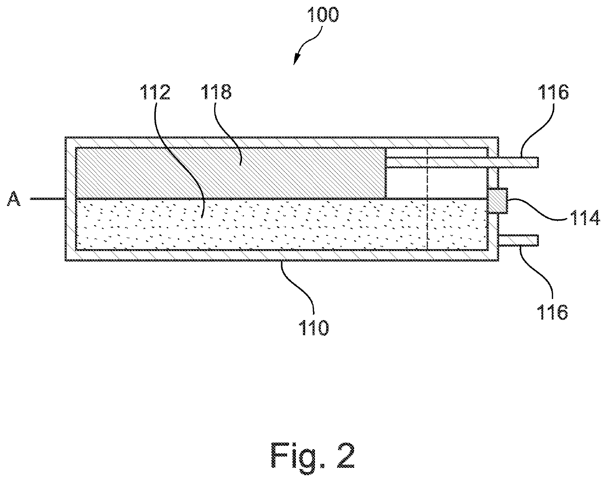
In the event that the heat battery is installed in horizontal planes, it has been found that such arrangements are very inefficient and significant performance drops are encountered.

Method used


Image

  • Improved heat battery
  • Improved heat battery
  • Improved heat battery

Examples


Embodiment Construction

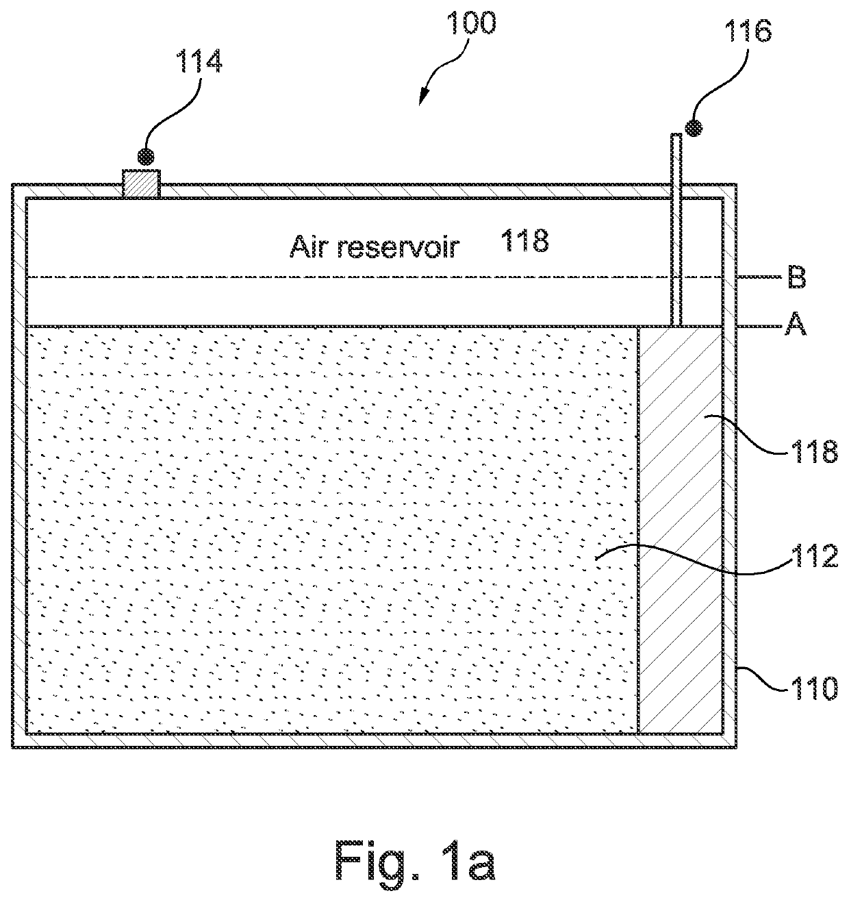
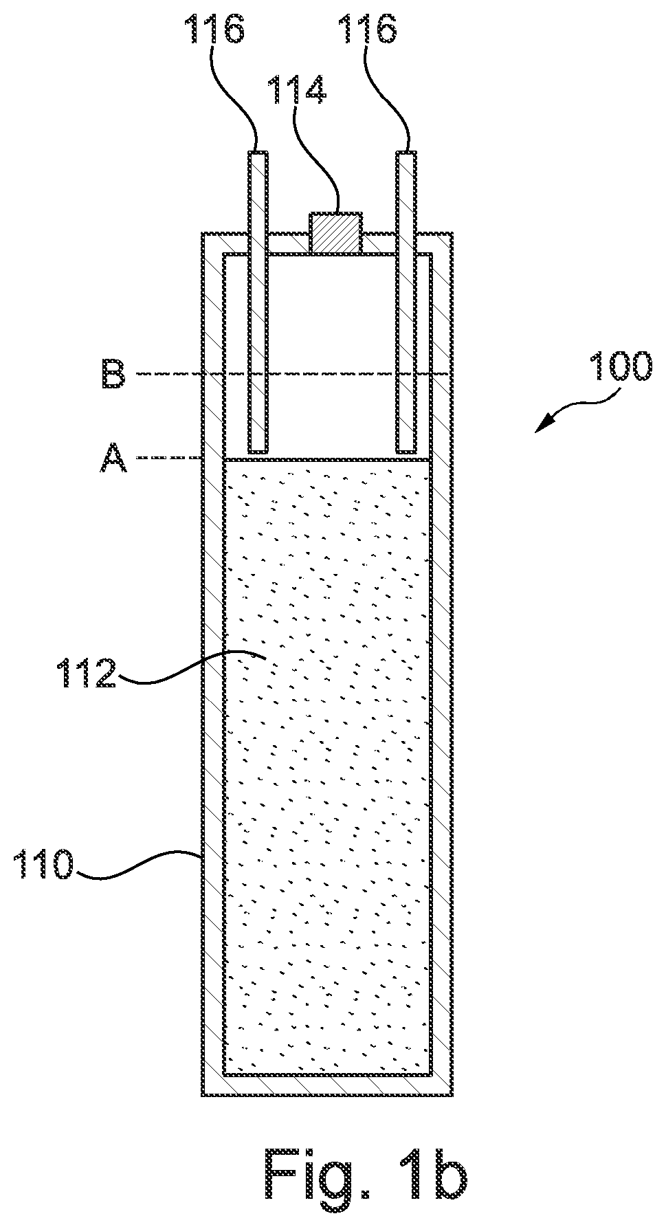
[0101]A representation of a prior art heat battery design generally designated 100 is shown in FIGS. 1a and 1b. The heat battery 100 in both FIGS. 1a and 1b is positioned in a vertical or a substantially vertical orientation.

[0102]FIG. 1a is a sectional side view of the heat battery 100 and FIG. 1b is a sectional end view of the heat battery 100.

[0103]As shown in FIGS. 1a and 1b, the heat battery 100 comprises a battery cell case 110. Contained within the battery cell case 110 there is PCM 112 and a heat exchanger 118. The PCM 112 fills about three quarters of the battery cell case 110.

[0104]FIGS. 1a and 1b also show that there is a filling port 114 located on an upper side of the battery cell case 110. The filling port 114 may be used as an inlet to pour material such as PCM into the battery cell case 110. The filling port 114 may be closed using any form of closure device such as a stopper.

[0105]There is also shown a series of battery flow and return pipes 116 which may be used in...


PUM


Abstract

There is herein described a heat battery design for horizontal and vertical planes and a heat battery using a separate volume compensator. In particular, there is described an improved heat battery design which overcomes the problem of over-pressurisation within a battery cell during use.

Description

FIELD OF THE INVENTION[0001]The present invention relates to a heat battery design capable of overcoming over-pressurisation problems for both horizontally and vertically oriented heat batteries. The heat battery may comprise an expandable device or alternatively a separate volume compensator which is capable of controlling the pressure inside the heat battery.BACKGROUND OF THE INVENTION[0002]There is a need in the field to provide an improved heat battery arrangement which is capable of controlling the pressure inside a heat battery and, in particular, a phase change material (PCM) heat battery.[0003]In the prior art and when a heat battery is depleted, the transfer of heat within the battery can lead to changes in the level of the phase change material (i.e. PCM). The PCM level may be found to rise and compress air reservoirs within the battery cell. This may lead to over-pressurisation and damage occurring to the battery cell. This can have a detrimental effect on both the effici...

Claims


Application Information

Patent Timeline
IPC IPC(8): F28D20/02
CPCF28D20/021F28D2020/0078F28D20/028F28D20/02F28F2265/14Y02E60/14Y02E60/10
Inventor ZAGLIO, MAURIZIOGATAORA, SANTOKH SINGHBISSELL, ANDREW
Owner SUNAMP
Learn More