
Kitchen Air Conditioning System

a technology for air conditioning systems and kitchens, which is applied in ventilation systems, heating types, and domestic stoves or ranges. it can solve the problems of destroying decoration, bringing great discomfort to the cook, and insufficient compact structure, so as to achieve the effect of quick heat removal

Pending Publication Date: 2021-10-07
NINGBO FOTILE KITCHEN WARE CO LTD
View PDF0 Cites 1 Cited by
  • Summary
  • Abstract
  • Description
  • Claims
  • Application Information

AI Technical Summary

Benefits of technology

This patent describes a new kitchen air-conditioning system that has a secondary refrigerant pipe on the condenser of the air-conditioning assembly. This allows the secondary refrigerant to exchange heat with the refrigerating medium in the condenser. The system also includes heat dissipation units that quickly take away heat generated by the condenser of the air-conditioning assembly. This results in more efficient cooling for the kitchen.

Problems solved by technology

Especially in summer, the sultry kitchen environment brings great discomfort to the cook.
Such a connection requires the formation of a hole on the wall, which destroys the decoration.
Since the outdoor unit is hung outdoors, the structure is not compact enough and it is less aesthetically pleasing.
When the portable air conditioner is used, it needs to be manually connected to the heat dissipation hose, and then the hose needs to be placed outside the window, which is inconvenient to use.
Although the square hole may be blocked with other things, it is messy and it destroys the decoration.
Therefore, the heat dissipation of the kitchen air conditioner becomes a challenging problem.
If the in-time heat dissipation of the kitchen air conditioner fails during its use, the energy efficiency of the air conditioner will be greatly reduced.
However, the existing kitchen air conditioner and the range hood operate independently of each other, and they cannot be linked.
The heat energy generated by the kitchen air conditioner cannot be exhausted to the outside through the fan of the range hood.
Therefore, how to exhaust the heat energy generated by the kitchen air conditioner through the range hood becomes an urgent problem.

Method used


Image

  • Kitchen Air Conditioning System
  • Kitchen Air Conditioning System
  • Kitchen Air Conditioning System

Examples


Embodiment Construction

[0022]The present invention will be further described below in detail with reference to the accompanying drawings by embodiments.

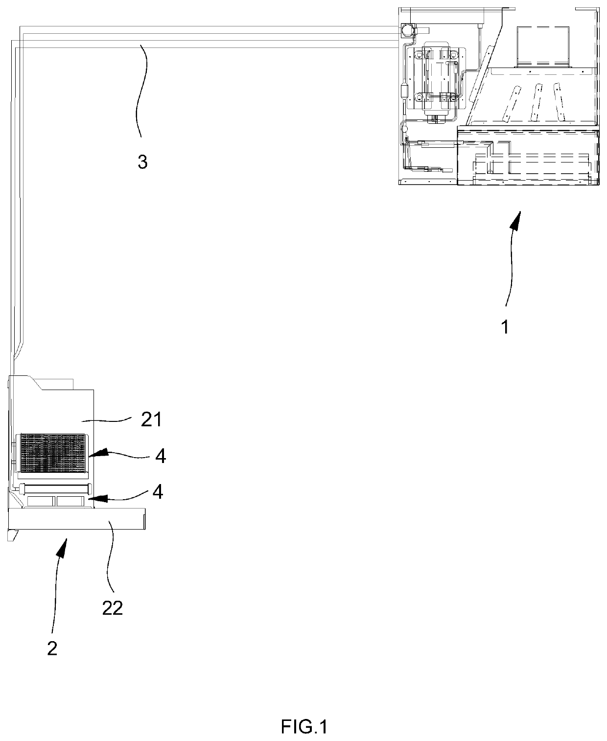
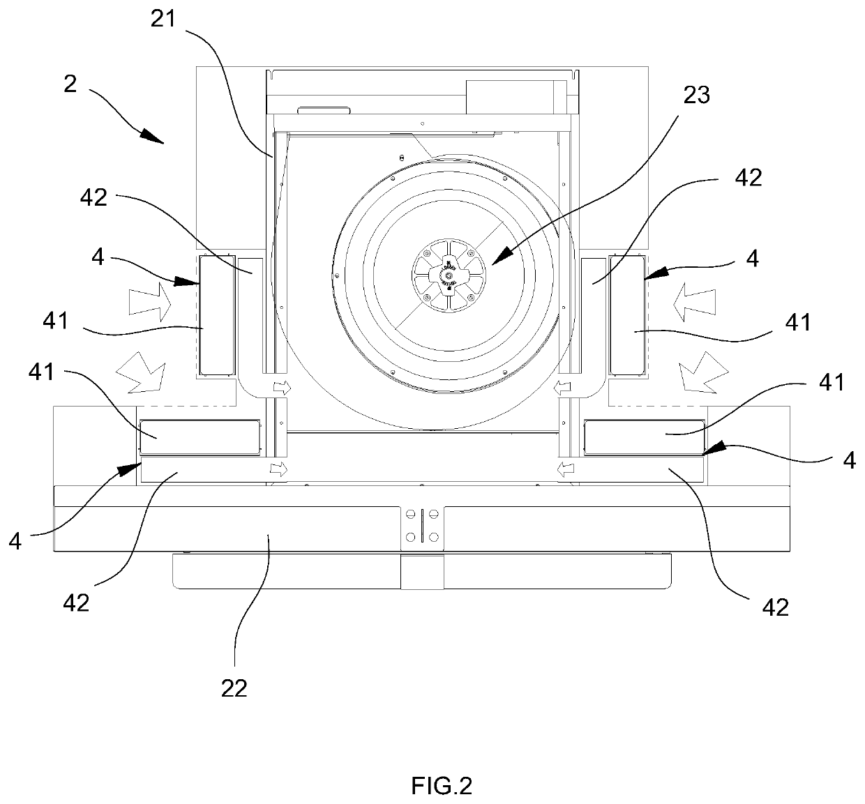
[0023]FIGS. 1 to 3 show an embodiment of a kitchen air-conditioning system. The kitchen air-conditioning system in this embodiment comprises an air-conditioning assembly 1 and a range hood assembly 2. The air-conditioning assembly 1 comprises a compressor 11, an evaporator 12 and a condenser 13 which are connected with each other through a plurality of refrigerating medium pipes 14. The specific structure of the air-conditioning assembly 1 can refer to the existing air conditioner and will not be described here.

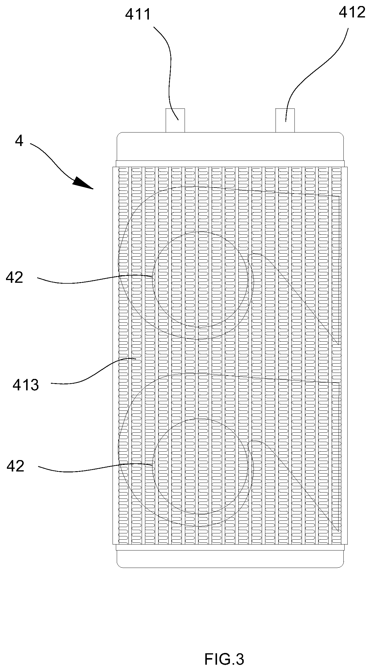
[0024]The condenser 13 and the range hood assembly 2 are connected through a secondary refrigerant pipe 3, the secondary refrigerant pipe 3 has secondary refrigerant for heat exchange with refrigerating medium inside the condenser 13; a heat dissipation unit 4 in communication with the secondary refrigerant pipe 3 is disposed on the range hood assem...


PUM


Abstract

A kitchen air-conditioning system comprises an air-conditioning assembly (1) and a range hood assembly (2). The air-conditioning assembly (1) comprises a compressor (11), an evaporator (12) and a condenser (13) which are connected with each other through a plurality of refrigerating medium pipes (14); the condenser (13) and the range hood assembly (2) are connected through a secondary refrigerant pipe (3), a heat dissipation unit (4) in communication with the secondary refrigerant pipe (3) is disposed on the range hood assembly (2). The secondary refrigerant pipe (3) on the condenser has a secondary refrigerant inlet and a secondary refrigerant outlet, and the secondary refrigerant in the secondary refrigerant pipe (3) can exchange heat with the refrigerating medium in the condenser (13), and the heat dissipation units (4) connected to the secondary refrigerant pipe (3) can quickly take away heat generated by the condenser.

Description

TECHNICAL FIELD OF THE INVENTION[0001]The present invention relates to a kitchen air-conditioning system.BACKGROUND OF THE INVENTION[0002]As a main place for people to cook, the kitchen air environment directly affects the mood of the cook. Especially in summer, the sultry kitchen environment brings great discomfort to the cook. Accordingly, various kitchen air-conditioners have been proposed to cool the kitchen.[0003]There is no significant difference between the existing kitchen air-conditioners and common air conditioners. There are generally two forms of kitchen air-conditioners. One form is split kitchen air-conditioner. That is, the outdoor unit is located outdoors, the indoor unit is located indoors, and the indoor and outdoor units each have a motor fan. The connection of the indoor and outdoor units in the split kitchen air-conditioner is realized by pipelines. Such a connection requires the formation of a hole on the wall, which destroys the decoration. Since the outdoor u...

Claims


Application Information

Patent Timeline
Patent Type & Authority Applications(United States)
IPC IPC(8): F24F13/02F24F13/06
CPCF24F13/0227F24F2221/18F24F13/06F24C15/20F24F13/30F24F1/0011F24F1/0059F24F11/65F24F11/84F24F13/02F24F7/08F24F13/20F24F3/044F24F2003/0446F24F3/06F24F5/0096F24F1/0063F24F1/0323F24C15/2035
Inventor LI, ANGFU, HAIFENGZHU, QIHUICAO, YAQUNYU, BINGSONG
Owner NINGBO FOTILE KITCHEN WARE CO LTD
Learn More