Intensity modulated proton therapy plan optimization for localized plan deficiencies

Pending Publication Date: 2021-09-30
KONINKLJIJKE PHILIPS NV
View PDF0 Cites 0 Cited by
  • Summary
  • Abstract
  • Description
  • Claims
  • Application Information

AI Technical Summary

Benefits of technology

The current invention provides a way for physicians to optimize the initial therapy play for proton therapy treatment. It also addresses the need to improve the robustness of the treatment plan for localized dose deficiencies while maintaining overall plan quality. The invention identifies critical proton spots and translates them into local plan deficiency areas, allowing for robust optimization of these areas only. This improves the plan's ability to withstand patient movement and organ deformation during treatment delivery. Overall, the invention provides more options for physicians and makes proton therapy treatment more robust and effective.

Problems solved by technology

IMPT treatment can take significant time to deliver, e.g. half an hour.
Critical proton spots are the proton spots that have a high risk of delivering a deviant dose, e.g. too high or too low in view of the clinical goals, in case an error, such as a setup, range or LRE error, occurs.

Method used


Image

  • Intensity modulated proton therapy plan optimization for localized plan deficiencies
  • Intensity modulated proton therapy plan optimization for localized plan deficiencies
  • Intensity modulated proton therapy plan optimization for localized plan deficiencies

Examples


Embodiment Construction

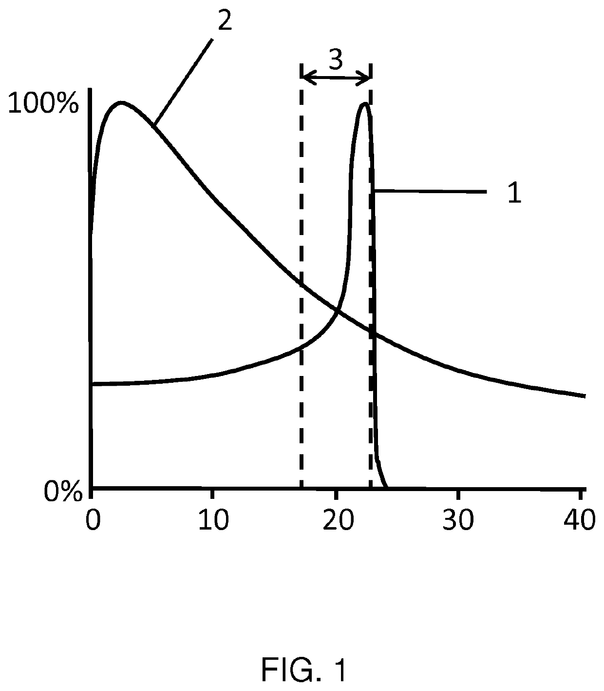
[0035]FIG. 1 illustrates the shape of a Bragg-peak for a proton beam 1. Beam intensity is shown as a function of penetration depth. For comparison, the intensity profile of a conventional X-ray beam 2 used for radiation therapy is also shown. In this figure, the vertical axis shows percentage of intensity and the horizontal axis shows penetration depth in cm. The target structure 3 is located between the dashed lines around 20 cm beneath the patient's skin. As can be seen in the figure, the proton beam 1 delivers a high intensity within the target structure 3 and a lower intensity at and directly beneath the skin. In particular when compared to the conventional X-ray beam 2. FIG. 1 also shows the sharp fall-off of the intensity of the proton beam at the right-hand side of the target structure 3. This shape allows for high precision of delivery compare to the conventional X-ray beam 2, but it also has particular sensitivity to errors such as range and setup uncertainties. In case the...


PUM


Abstract

A method and system for optimizing an IMPT plan are provided, as well as a computer program product for performing, and an arrangement for planning IMPT. For optimizing the IMPT plan, the following steps are performed. An initial IMPT plan is received, along with anatomical image data of the subject to be treated. Critical proton spots are identified in the initial plan using the anatomical image data. At least one local plan deficiency area associated with the identified critical proton spots is generated. A local treatment plan is then generated for the LPDA by applying robust optimization to it. The optimized treatment plan for delivery to the subject to is then generated by combining the local treatment plan with the initial IMPT plan.

Description

FIELD OF THE INVENTION[0001]The invention generally relates to planning intensity modulated proton therapy (IMPT). In particular the invention relates to optimizing an IMPT plan. More specifically, the invention relates to optimizing an IMPT plan with localized plan deficiencies.BACKGROUND OF THE INVENTION[0002]In intensity modulated proton therapy (IMPT), target structures in a patient's body, such as tumors, are treated by subjecting them to irradiation by a beam of protons. The treatment is delivered in such a way that the dose that is delivered to the target structures (TSs) is as high as possible, while at the same time the dose delivered to the surrounding healthy tissue and structures, usually referred to as organs at risk (OARs), is as low as possible. A tradeoff between the two will have to be made. For this, clinical goals are provided. Clinical goals in planning the IMPT treatment will specify the requirements for dose to be delivered to a TS. The clinical goals may also ...

Claims


Application Information

Patent Timeline
IPC IPC(8): A61N5/10
CPCA61N5/1031A61N2005/1087A61N5/103A61N5/1039
Inventor RANGANATHAN, VAITHEESWARANPERUMAL, BOJARAJAN
Owner KONINKLJIJKE PHILIPS NV
Why Eureka
Try Eureka