Displacing apparatus and automobile calibration device

a technology for displacing apparatus and automobiles, applied in the direction of instruments, machine supports, transportation and packaging, etc., can solve the problems of excessive friction and unsmooth displacement, light load, and the displacing assembly can bear a relatively heavy load, so as to reduce friction, facilitate assembly, and move more smoothly

Inactive Publication Date: 2021-09-23
AUTEL UNITED CREATION SOFTWARE DEV CO LTD
View PDF0 Cites 1 Cited by
  • Summary
  • Abstract
  • Description
  • Claims
  • Application Information

AI Technical Summary

Benefits of technology

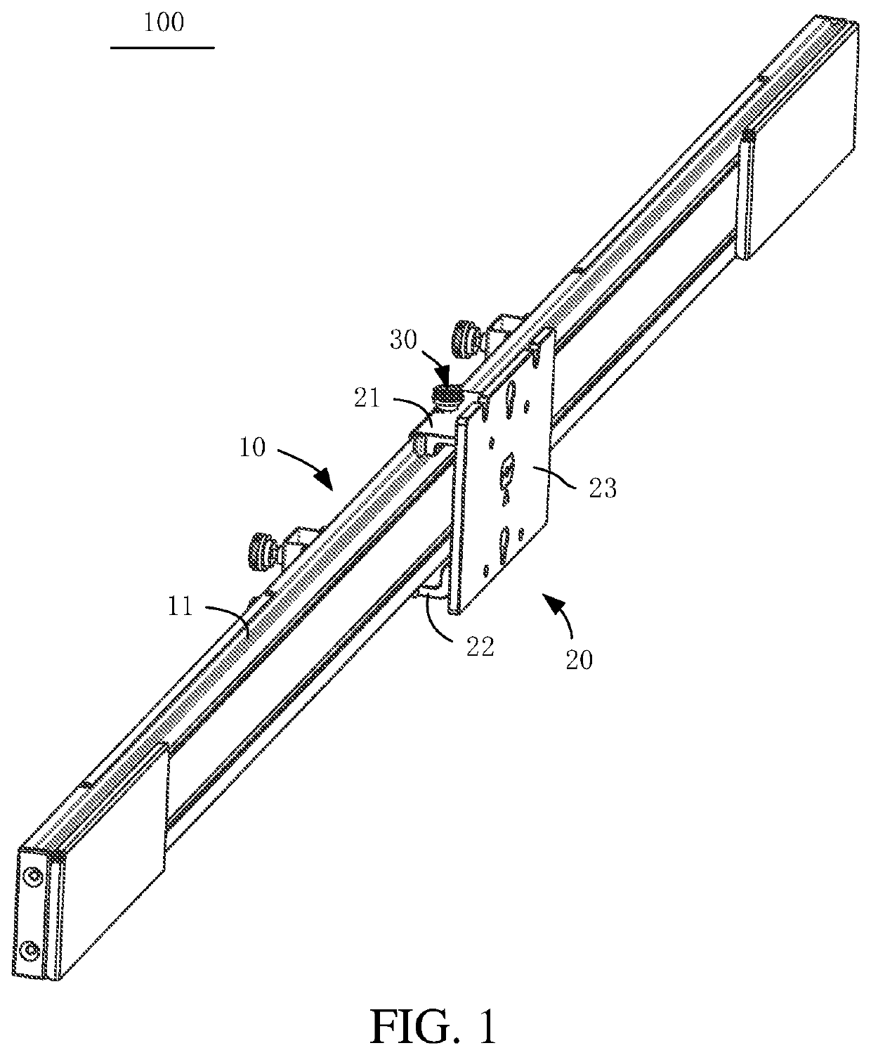
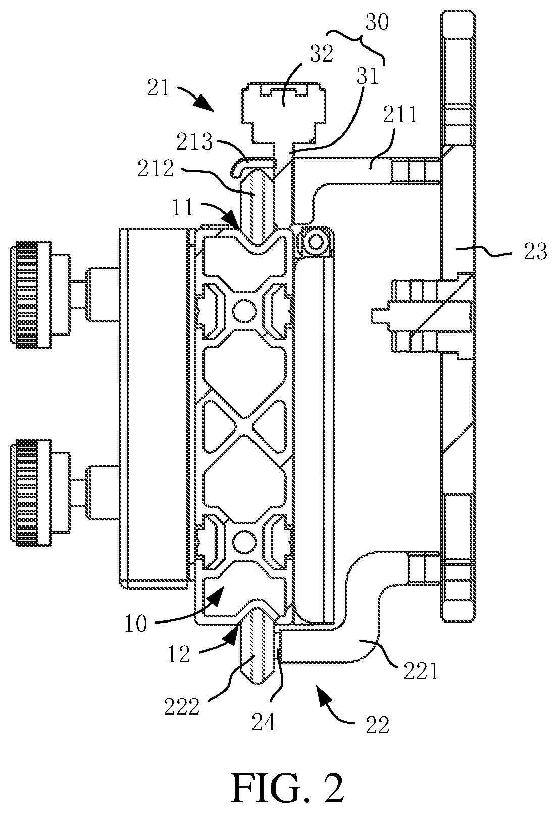
The present application provides a displacing apparatus and an automobile calibration device to solve the technical problem of being unaffordable, inconveniently installation and high cost. The guide rail serves as a base, and the first and second guide grooves are formed on the surface of the base. The first and second rolling mechanisms are rollably mated with the guide rail to reduce friction between the displacing assembly and the guide rail through rolling. The first and second rolling mechanisms are jointly clamped on the guide rail, and restrain each other to avoid overturning, so that the displacing assembly can still move smoothly even under a relatively heavy load and has good stability. The displacing apparatus of the present application can make full use of the profile structure of the guide rail, so that the displacing assembly can bear a relatively heavy load.

Problems solved by technology

During implementation of the present application, the inventor finds that: it is inconvenient to install the guide rail slider with the T-shaped groove due to high requirement for installation surface, high cost, and the heavy weight; also, the T-shaped groove may only afford a light load, and would cause excessive friction and unsmooth displacement.
Further, the displacing apparatus of the present application can make full use of the profile structure of the guide rail, so that the displacing assembly can bear a relatively heavy load.

Method used


Image

  • Displacing apparatus and automobile calibration device
  • Displacing apparatus and automobile calibration device
  • Displacing apparatus and automobile calibration device

Examples


Embodiment Construction

[0033]The technical solutions in embodiments of this application are clearly and completely described in the following with reference to the accompanying drawings in the embodiments of this application. Apparently, the described embodiments are merely some rather than all of the embodiments of this application. All other embodiments obtained by a person of ordinary skill in the art based on the embodiments of the present application without creative efforts shall fall within the protection scope of this application.

[0034]Unless otherwise defined, meanings of all technical and scientific terms used in this specification are the same as those usually understood by a person skilled in the art to which this application belongs. If description, for example, “first” and “second” is involved in the embodiments of this application, the description, for example, “first” and “second”, is merely intended for a purpose of description, and shall not be understood as an indication or implication ...


PUM


Abstract

The present application provides a displacing apparatus and an automobile calibration device. The displacing apparatus includes a guide rail and a displacing assembly. A first guide groove and a second guide groove are formed on a surface of the guide rail. The displacing assembly comprises a first rolling mechanism, a second rolling mechanism and a connecting portion. The first rolling mechanism and the second rolling mechanism are mounted to the connecting portion. The first rolling mechanism is rollably mated with the first guide groove and the second rolling mechanism is rollably mated with the second guide groove. The first rolling mechanism and the second rolling mechanism are jointly clamped on the guide rail and are rollable relative to the guide rail. In the technical solutions of the present application, the first rolling mechanism and the second rolling mechanism are jointly clamped on the guide rail and are rollably mated with the guide rail, so that the displacing assembly can be moved smoothly relative to the guide rail and the displacing assembly can be firmly assembled to the guide rail.

Description

[0001]The present application is a continuation application of International Patent Application No. PCT / CN2019 / 123053 filed on Dec. 4, 2019, which claims priority to Chinese Patent Application No. 201811488789.4 filed on Dec. 6, 2018, both of which are incorporated by reference herein in their entireties.BACKGROUNDTechnical Field[0002]The present application relates to the technical field of device calibration, and in particular, to a displacing apparatus and an automobile calibration device including the displacing apparatus.Related Art[0003]At present, a driver assistance system for a vehicle can be used to provide assistance for travelling of the vehicle to achieve intelligent travelling of the vehicle. The driver assistance system of the vehicle may include various sensors such as a radar or a camera to sense surroundings around the vehicle. Surroundings sensing accuracy of the sensors depends on positions of the sensors such as the radar and or camera on the vehicle. Therefore,...

Claims


Application Information

Patent Timeline
IPC IPC(8): F16M11/04G01S7/40
CPCF16M11/045F16M2200/028F16M11/046G01S7/40B60R11/00G01M17/007G01S7/4026G01S7/4086
Inventor LAI, BIWANG
Owner AUTEL UNITED CREATION SOFTWARE DEV CO LTD
Why Eureka
Try Eureka