Acoustic wave filter device and multiplexer using same
a filter device and multiplexer technology, applied in the direction of impedence networks, electrical devices, etc., can solve the problems of degrading bandpass characteristics and increasing insertion loss, and achieve the effect of reducing or preventing an increase in insertion loss, reducing the resistive component of the inductor, and relatively reducing the inductance of the inductor
- Summary
- Abstract
- Description
- Claims
- Application Information
AI Technical Summary
Benefits of technology
Problems solved by technology
Method used
Image
Examples
first preferred embodiment
Configuration of Multiplexer
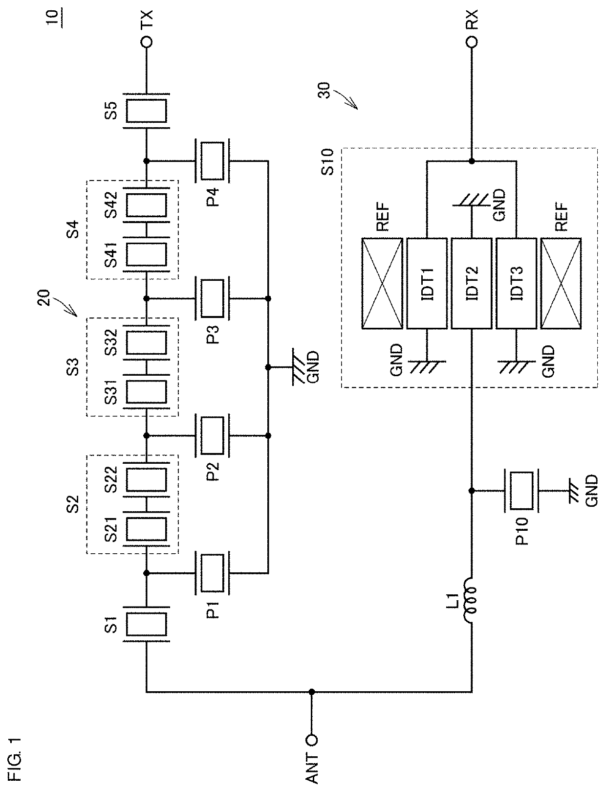
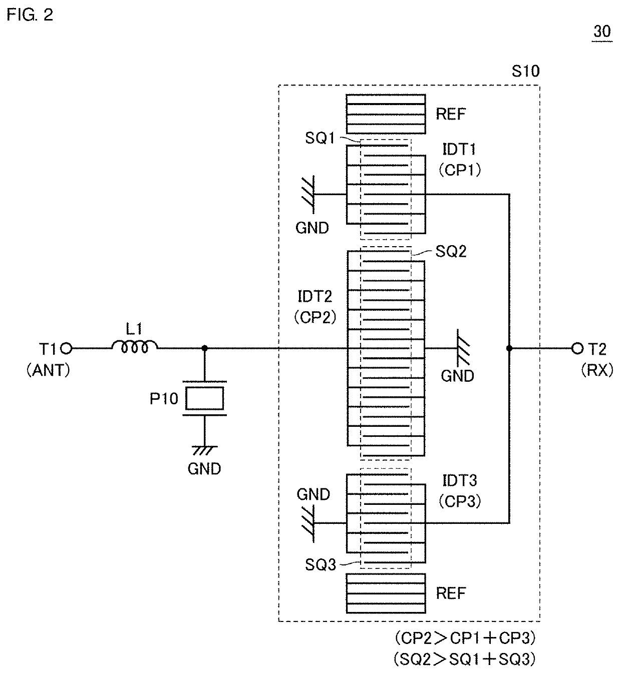
[0025]FIG. 1 is a diagram illustrating a circuit configuration of a multiplexer 10 including an acoustic wave filter device 30 according to a first preferred embodiment of the present invention. The multiplexer 10 further includes an acoustic wave filter device 20 in addition to the acoustic wave filter device 30. Note that, in the following description, “acoustic wave filter device” may also be simply referred to as “filter device”.
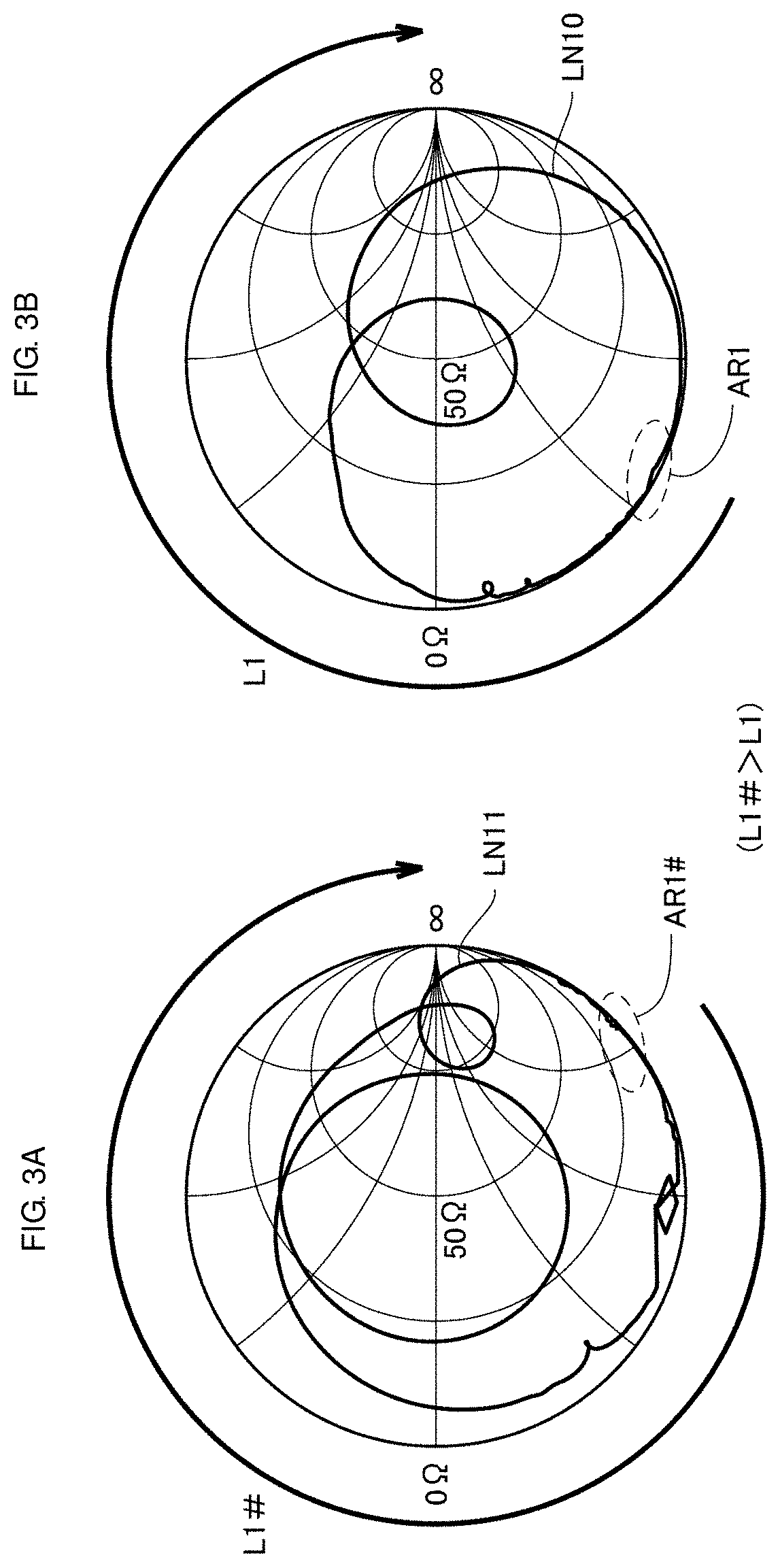
[0026]With reference to FIG. 1, the multiplexer 10 is an acoustic wave filter device used in, for example, a transmission-reception circuit of a communication device. The filter device 20 is provided between an antenna terminal ANT (a first terminal) and a transmission terminal TX (a third terminal), and the filter device 30 is provided between the antenna terminal ANT and a reception terminal RX (a second terminal). The filter device 20 is a band pass filter that treats the frequency band of a transmission signal as a pass ba...
second preferred embodiment
[0044]In the first preferred embodiment, the configuration has been described in which the capacitance of the IDT electrode coupled to the antenna terminal is increased based on the number of electrode fingers of the IDT electrode. In a second preferred embodiment of the present invention, a configuration will be described in which the capacitance of an IDT electrode coupled to the antenna terminal is increased based on a spacing between electrode fingers of the IDT electrode.
[0045]FIG. 4 is a diagram for describing an acoustic wave filter device 30A according to the second preferred embodiment. In the filter device 30A, the series arm resonance unit S10 in FIG. 2 is replaced with a series arm resonance unit S10A. In the filter device 30A, the description of the same or corresponding elements as those in FIG. 2 will not be repeated.
[0046]With reference to FIG. 4, similarly to the series arm resonance unit S10 in FIG. 2, the series arm resonance unit S10A is a longitudinally coupled ...
third preferred embodiment
[0054]It is known that, in a longitudinally coupled resonator acoustic wave resonator, different vibration modes of a signal propagating through IDT electrodes are generated by making the pitch of a portion of electrode fingers of an IDT electrode narrower than the pitch of the other portion of the electrode fingers of the IDT electrode. By generating these modes, the bandpass characteristics of a filter device can be improved.
[0055]In contrast, when the pitch of electrode fingers is reduced, the capacitance of the corresponding portion is increased, so that the capacitance of the IDT electrode can be increased.
[0056]In a third preferred embodiment of the present invention, the configuration of a filter device will be described with which the insertion loss of the filter device is reduced in a case where a longitudinally coupled resonator acoustic wave resonator includes an IDT electrode having a narrow-pitch portion.
[0057]FIG. 7 is a diagram for describing an acoustic wave filter d...
PUM
 Abstract
Description
Claims
Application Information
 - R&D
- Intellectual Property
- Life Sciences
- Materials
- Tech Scout
- Unparalleled Data Quality
- Higher Quality Content
- 60% Fewer Hallucinations
Browse by: Latest US Patents, China's latest patents, Technical Efficacy Thesaurus, Application Domain, Technology Topic, Popular Technical Reports.
© 2025 PatSnap. All rights reserved.Legal|Privacy policy|Modern Slavery Act Transparency Statement|Sitemap|About US| Contact US: help@patsnap.com


