Sound attenuator for a fluid flow line and method of manufacturing the same

Active Publication Date: 2021-09-09
UMFOTEC
View PDF2 Cites 0 Cited by
  • Summary
  • Abstract
  • Description
  • Claims
  • Application Information

AI Technical Summary

Benefits of technology

The present invention provides an improved sound attenuator and an improved method for its manufacture, which can achieve sufficient sound attenuation efficiency with small pipe diameters while maintaining the effectiveness of the IHU method. The expansion and constriction sections of the pipes are matched to each other, to ensure proper connection between them. The design allows for installation in piping systems with small cross-sections. Multiple axially adjacent resonator chambers can be used to target different frequency ranges. To prevent constriction of the pipes during sliding, the cylinder diameters of the contact surfaces vary monotonically as a function of their axial position.

Problems solved by technology

A problem with this application is the typically much smaller pipe cross-sections of the refrigerant line compared to the pipe cross-sections of conventional automotive exhaust lines.
Greater stretching comes with a risk of cracking of the material and / or excessively thin walls of the resulting formed pipe.
The above-mentioned connection by welding, which is particularly preferred for the terminal edge areas, can encounter technical difficulties at the inner contact areas due to the poor accessibility.
However, especially with cost-optimized production, manufacturing tolerances can lead to jamming of the pipes when they are slid on.

Method used


Image

  • Sound attenuator for a fluid flow line and method of manufacturing the same
  • Sound attenuator for a fluid flow line and method of manufacturing the same
  • Sound attenuator for a fluid flow line and method of manufacturing the same

Examples


Embodiment Construction

[0033]Identical reference numbers in the Figures indicate identical or analogous elements.

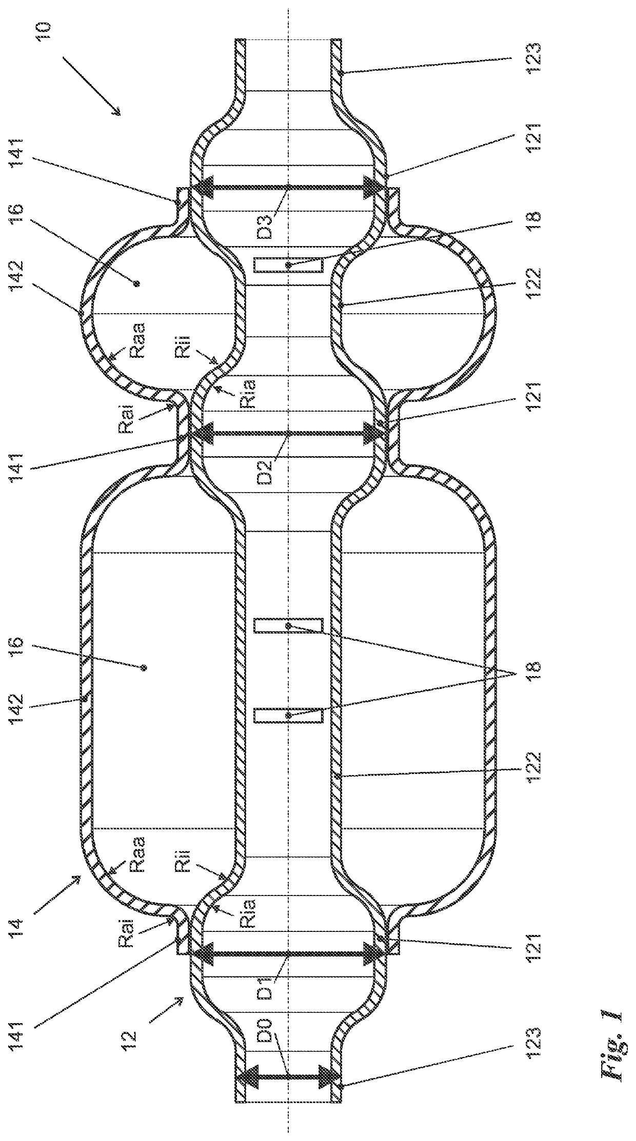
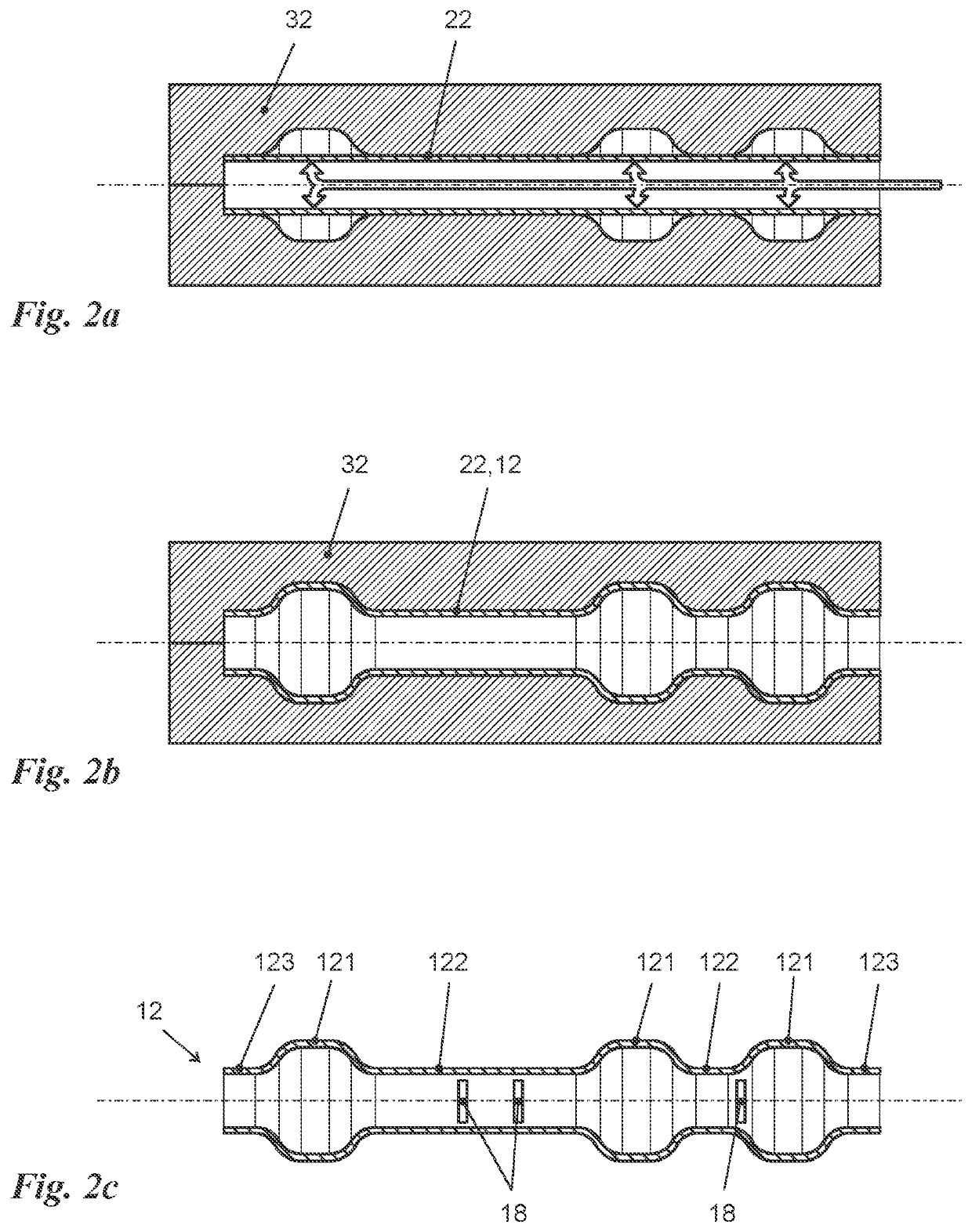
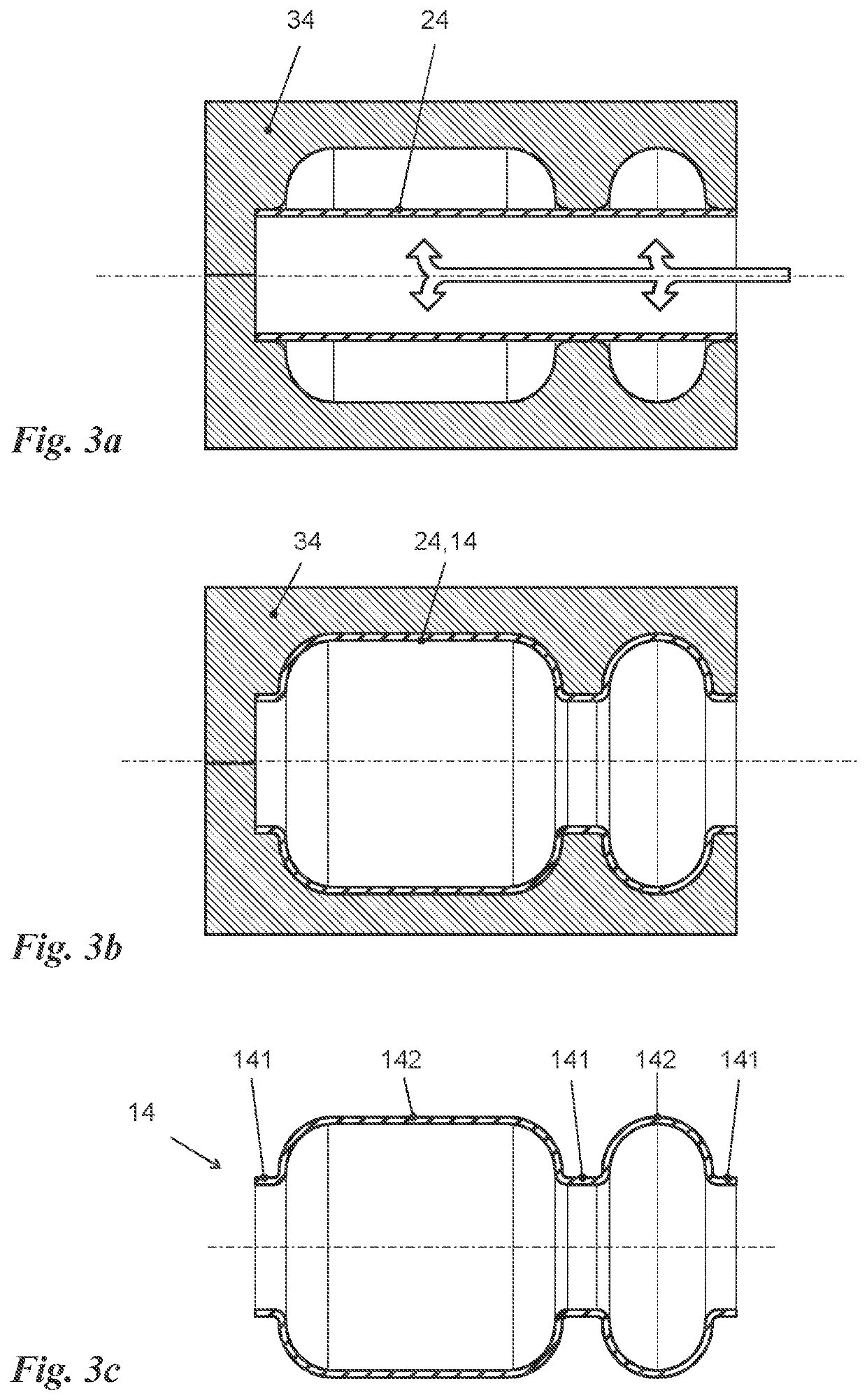
[0034]FIG. 1 is a cross-sectional view of one embodiment of a sound attenuator 10 according to the invention. The sound attenuator 10 substantially has an inner pipe 12 and an outer pipe 14. The inner pipe 12 passes coaxially through the outer pipe 14. The inner pipe 12 has three expansion sections 121. Intermediate inner pipe sections 122 are located between the expansion sections 121.

[0035]Connecting pieces 123 are located axially outside of the outer two expansion sections 121. The connecting pieces 123, as well as the intermediate inner pipe sections 122, have substantially the same diameter, which is significantly smaller than the diameter of the expansion sections 121. In particular, the ratio of the diameters of the expansion sections 121 to the diameters of the intermediate inner pipe sections 122 or the connecting pieces 123 may be in the range of 1.2 to 2, preferably in the range of 1...


PUM

PropertyMeasurementUnit
Pressureaaaaaaaaaa
Diameteraaaaaaaaaa
Shapeaaaaaaaaaa

Abstract

A sound attenuator has an inner pipe (12) with expansion sections (121) of enlarged diameter corresponding to the constriction sections (141) of an outer pipe (14). The expansion sections (121) in pairs axially delimit an intermediate inner pipe section (122) containing a wall opening (18) and having a reduced diameter relative to the expansion sections (121). The inner surface of the outer pipe (14) in each of its constriction sections (141) is connected to the outer surface of the inner pipe (12) in its respective corresponding expansion section (121). A method of manufacturing such a sound attenuator (10) also is provided and uses internal high-pressure forming.

Description

BACKGROUNDField of the Invention[0001]The invention relates to a sound attenuator fora fluid flow line comprising an inner pipe and an outer pipe coaxially encompassing the inner pipe. The outer pipe has an inner surface that is radially spaced from the outer surface of the inner pipe over the major part of its length. The outer pipe has at least two constriction sections of reduced diameter spaced apart from each other axially, and in which its inner surface is connected to the outer surface of the inner pipe to form at least one axially and radially outwardly closed ring chamber that is in fluid-exchanging contact with the interior of the inner pipe via at least one opening in the wall thereof.[0002]The invention further relates to a method of manufacturing a sound attenuator for a fluid flow line, comprising the steps of:[0003]providing an outer pipe blank,[0004]expanding the outer pipe blank in certain sections by means of an internal high-pressure forming method to produce an o...

Claims


Application Information

Patent Timeline
IPC IPC(8): G10K11/16B21D39/04
CPCG10K11/161B21D39/04F16L55/0335F16L55/0336F01N1/003F01N1/02F01N13/1883F01N1/026F01N1/023
Inventor LINKE, BEREND
Owner UMFOTEC
Why Eureka
Try Eureka