Linear guide rail structure

a guide rail and linear technology, applied in the direction of linear bearings, shafts and bearings, bearings, etc., can solve the problems of difficult to keep the surface of the guide rail smooth, the rigid body of the slider cannot run smoothly, and the phenomenon of dust and dirt accumulation, etc., to achieve the effect of stable fixing effect and stable fixing

Active Publication Date: 2021-08-26
CHIEFTECH PRECISION
View PDF5 Cites 0 Cited by
  • Summary
  • Abstract
  • Description
  • Claims
  • Application Information

AI Technical Summary

Benefits of technology

[0026]4. The locking member includes a fastener and at least one pressure-exerting block. The fastener has a flat portion and an inwardly bent portion that is bent and retracted inwardly from either side of the flat portion. The inwardly bent portion is fastened to a recess below the top surface

Problems solved by technology

In actual use, dust or oil stains often accumulate in the bolt holes, so that when the rigid body of the slider passes through the position of the bolt hole, the dust and dirt enter the rigid body of the slider to hinder the rolling of the rollers in the rigid body of the slider, causing the rigid body of the slider not to run smoothly.
For assembly, in addition to inserting the bolt hole caps into the bolt holes in sequence, it is difficult to keep the surface of the guide rail smooth due to processing tolerances and there is still a phenomenon of accumulation of dust and dirt because the bolt hole caps are inserted into the bolt holes.
Besides, the force from the rigid body of the slider when running on the bolt hole caps will cause the bolt hole cap to sink, leading to accumulation of dust and dirt in the gap.
In the foregoing two methods, the engaging portion or the inert of the dustproof cover has been deformed and engage

Method used


Image

  • Linear guide rail structure
  • Linear guide rail structure
  • Linear guide rail structure

Examples


first embodiment

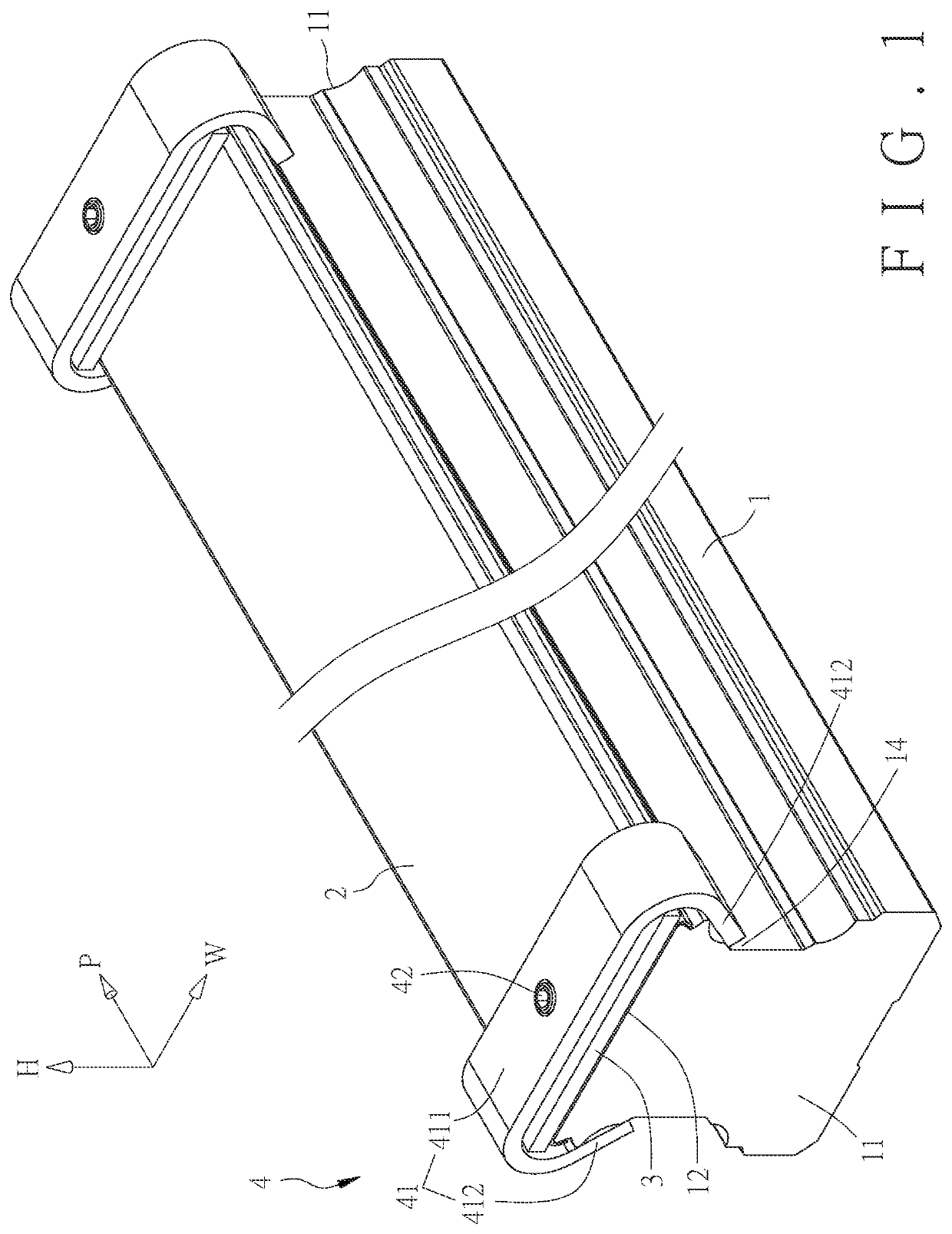
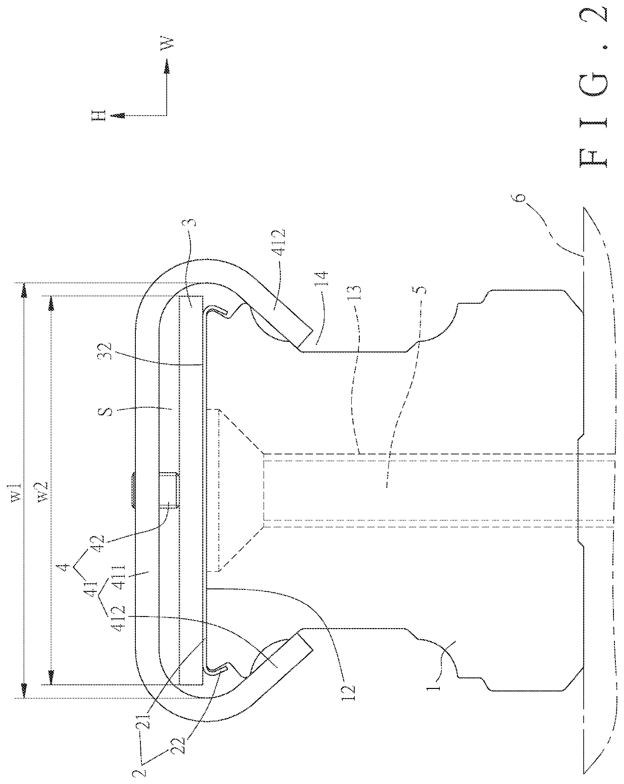
[0041]As shown in FIG. 1 and FIG. 2, the present invention comprises a guide rail (1) and a dustproof cover (2) on the guide rail (1). Each of two end portions (11) of the guide rail (1) has a pressure-exerting plate (3) and a locking member (4) for locking the dustproof cover (2).

[0042]The guide rail (1) extends along an axial direction (P). Two opposing ends of the guide rail (1) in the axial direction (P) are defined as the two end portions (11). The guide rail (1) has a top surface (12). The guide rail (1) has at least one locking hole (13) extending from the top surface (12) in a height direction (H) perpendicular to the axial direction (P). In this embodiment, the locking hole (13) is a screw hole. The dustproof cover (2) is in the form of a strip. The dustproof cover (2) extends along the axial direction (P). The dustproof cover (2) covers the top surface (12) of the guide rail (1). The pressure-exerting plate (3) is disposed on either end portion (11) of the guide rail (1) a...

second embodiment

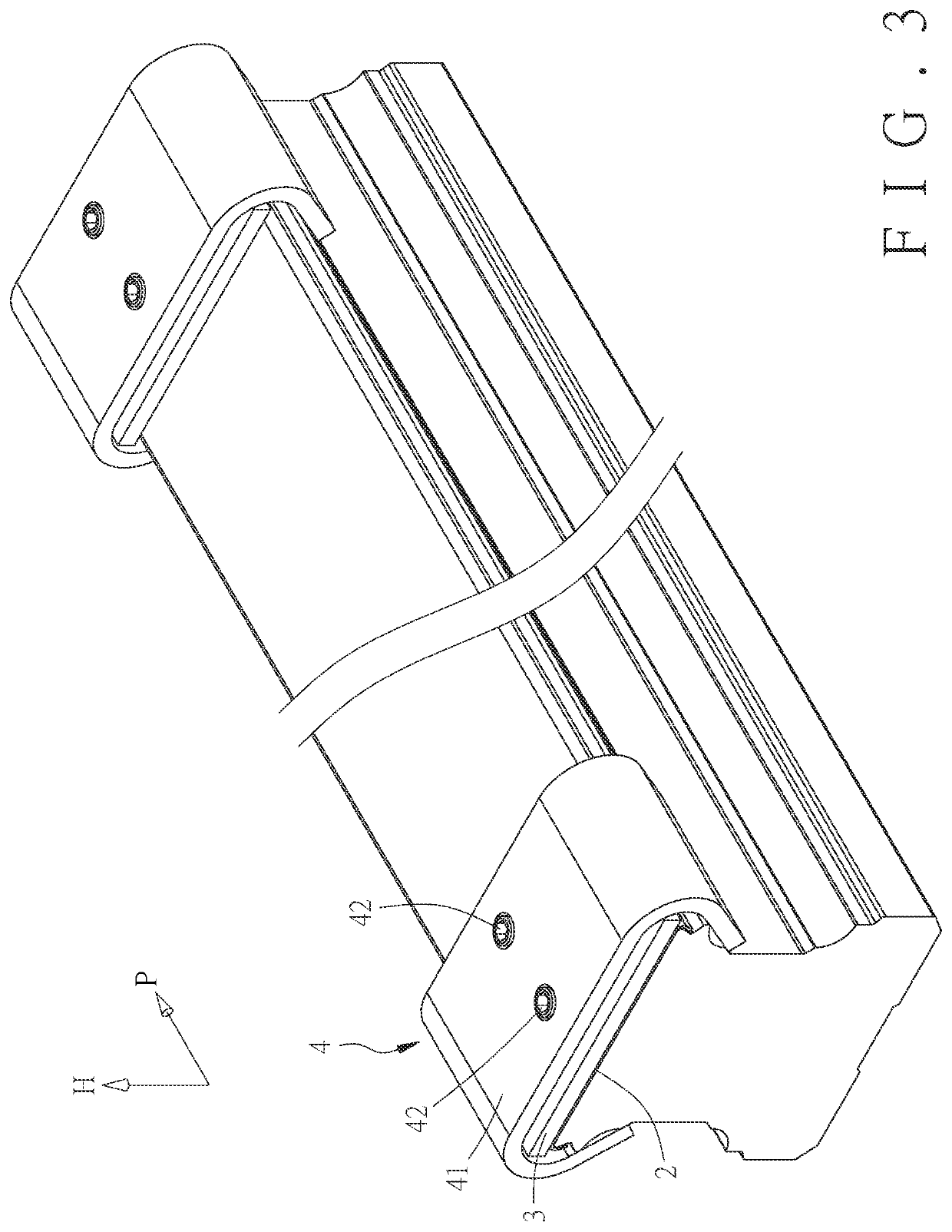
[0044]FIG. 3 shows the present invention. The second embodiment is substantially similar to the first embodiment with the exceptions described below. In this embodiment, the locking member (4) has two pressure-exerting blocks (42) in the axial direction (P) to be locked into the fastener (41) for pressing against the pressure-exerting plate (3) in the height direction (H). Thereby, the dustproof cover (2) is more firmly fixed.

third embodiment

[0045]FIG. 4 and FIG. 5 show the present invention. The third embodiment is substantially similar to the first embodiment with the exceptions described below. In this embodiment, the locking member (4) has two pressure-exerting blocks (42). After the two pressure-exerting blocks (42) are locked into the fastener (41), they abut against two opposing sides of the pressure-exerting plate (3) in the width direction (W). In this embodiment, the pressure-exerting blocks (42) abut against the pressure-exerting plate (3) in the width direction (W), accounting for 10% to 20% of the width of the pressure-exerting plate (3) near the side edges, which is the position of the dustproof cover (2) with better rigidity. By means of evenly locking the two opposing sides of the pressure-exerting plate (3), the dustproof cover (2) can be fixed more firmly.


PUM


Abstract

A linear guide rail structure includes a guide rail, a dustproof cover, a pressure-exerting plate, and a locking member. The guide rail extends along an axial direction. The guide rail has at least one locking hole extending from a top surface in a height direction perpendicular to the axial direction. The dustproof cover is disposed on the top surface of the guide rail to cover the locking hole. The pressure-exerting plate is disposed on an end portion of the guide rail to press against the dustproof cover. The locking member includes a fastener and at least one pressure-exerting block. The fastener is fixed to the end portion of the guide rail. The pressure-exerting block is locked into the fastener in the height direction to abut against the pressure-exerting plate in the height direction, so that the pressure-exerting plate is pressed against the dustproof cover.

Description

FIELD OF THE INVENTION[0001]The present invention relates to a linear guide rail structure, and more particularly to a guide rail having a pressure-exerting plate and a locking member at its end portion for directly applying a force in a height direction to fix a dustproof cover.BACKGROUND OF THE INVENTION[0002]A linear guide rail is generally formed with a plurality of bolt holes arranged along the axial direction of the guide rail. When in use, the guide rail is fixed on a working platform with bolts. In actual use, dust or oil stains often accumulate in the bolt holes, so that when the rigid body of the slider passes through the position of the bolt hole, the dust and dirt enter the rigid body of the slider to hinder the rolling of the rollers in the rigid body of the slider, causing the rigid body of the slider not to run smoothly. Therefore, in order to avoid this phenomenon, bolt hole caps or dustproof covers are provided to cover the bolt holes so as to reduce accumulation of...

Claims


Application Information

Patent Timeline
IPC IPC(8): F16C29/02
CPCF16C29/02F16C29/005F16C29/08F16C29/082F16C35/04
Inventor HSU, MING-CHE
Owner CHIEFTECH PRECISION
Why Eureka
Try Eureka