Monitor device for a lighting arrangement, a driver using the monitoring arrangement, and a driving method

a monitoring device and lighting arrangement technology, applied in lighting devices, electrical devices, light sources, etc., can solve the problems of voltage dips of power supplies, visual flashing, and increased current drawn by lighting loads, and achieve the effect of constant light output flux

Active Publication Date: 2021-08-19
SIGNIFY HLDG BV
View PDF0 Cites 2 Cited by
  • Summary
  • Abstract
  • Description
  • Claims
  • Application Information

AI Technical Summary

Benefits of technology

The patent describes a device that can monitor the use of power in a lighting arrangement by measuring the resistance of the wires between a power supply and the lights. This allows for more accurate determination of power consumption and enables the lights to be controlled more efficiently based on their electrical characteristics. The device can also help in identifying any leaks or damage in the wires, which can help to save energy and prevent accidents.

Problems solved by technology

The disadvantage of such a voltage-based lighting system is that the lighting load can draw more current than the rated power of the power supply.
However, this results in visual flashing.
Moreover sudden load steps might result in voltage dips of the power supply.
In some voltage-based systems, a dip in voltage translates into a dip in current and hence the current is not well probed and the actual power is then not estimated correctly.
Measuring current while not having a constant DC voltage of e.g. 24V (while assuming it is a fixed value of 24V) causes a measurement error.

Method used


Image

  • Monitor device for a lighting arrangement, a driver using the monitoring arrangement, and a driving method
  • Monitor device for a lighting arrangement, a driver using the monitoring arrangement, and a driving method
  • Monitor device for a lighting arrangement, a driver using the monitoring arrangement, and a driving method

Examples


Embodiment Construction

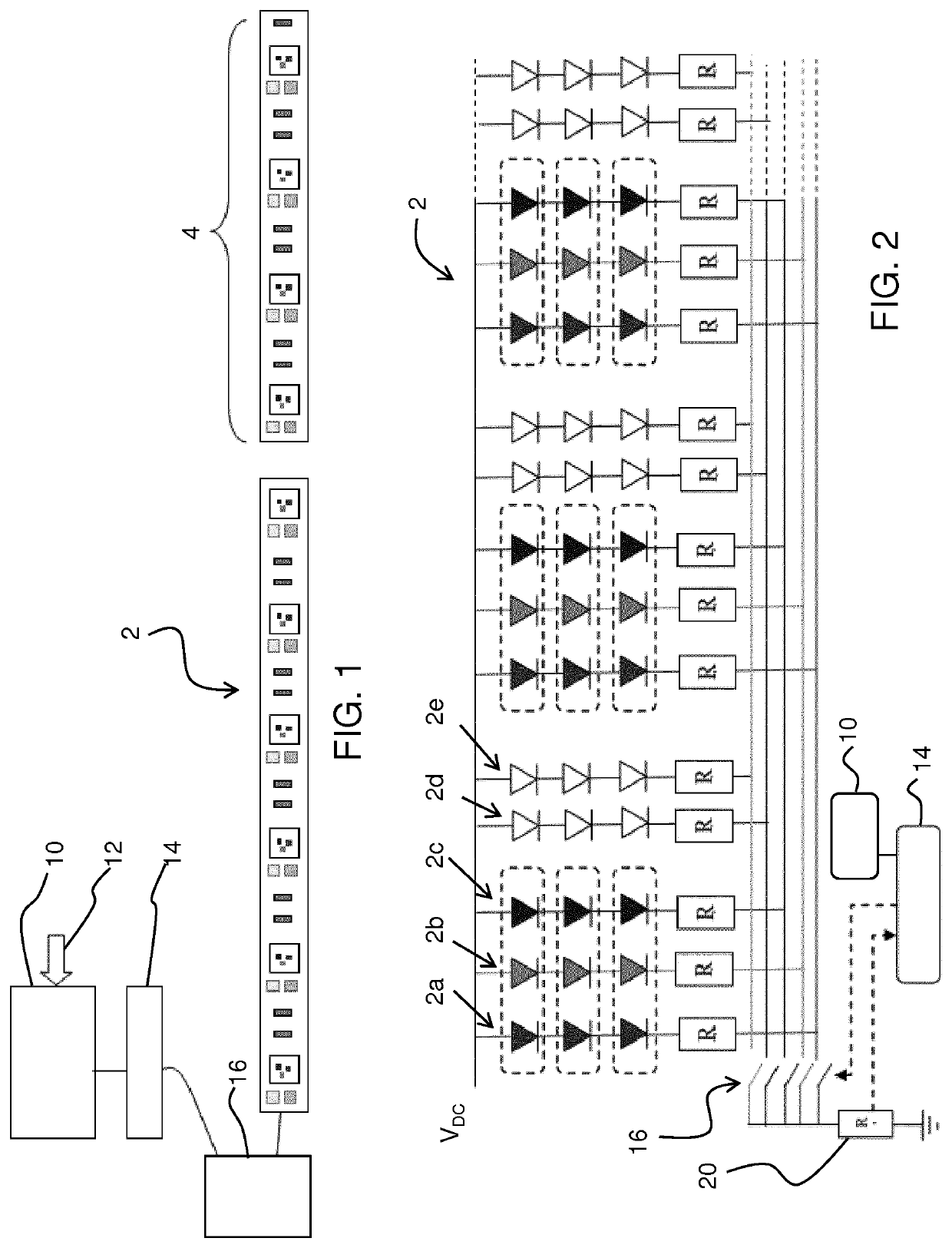
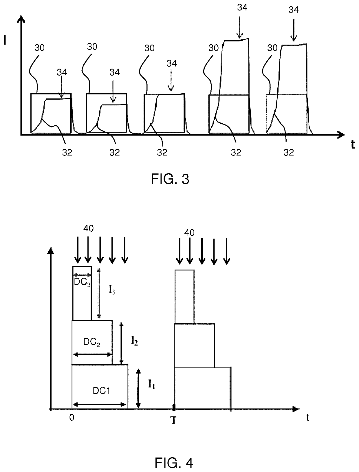
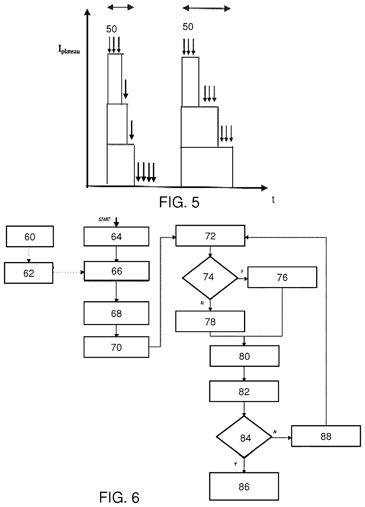
[0102]The invention provides a monitor device for monitoring a lighting arrangement of lighting elements of unknown electrical load, and a driver using the monitoring arrangement. A set of duty cycles is applied to switches which control sub-sets of lighting elements thereby to create a desired light output (i.e. desired by a user, and applied as a user input). With this desired duty cycle setting, the current for an individual duty cycle period is monitored, in particular to detect variations in a current plateau level within the individual duty cycle period. This is used to determine electrical characteristics including at least a cable resistance between a power supply unit and the lighting arrangement. An accurate estimation of the power consumption of the lighting arrangement (or more generally the load downstream of a power supply unit) may then be obtained. This avoids the need to probe the sub-sets of lighting elements individually in order to determine the nature of the loa...


PUM


Abstract

A monitor device is provided for monitoring a lighting arrangement of lighting elements of unknown electrical load, and a driver using the monitoring arrangement. A set of duty cycles is applied to switches which control sub-sets of lighting elements thereby to create a desired light output. With this desired duty cycle setting, the current for an individual duty cycle period is monitored, in particular to detect variations in a current plateau level within the individual duty cycle period. This is used to determine electrical characteristics or parameters including at least a cable resistance between a power supply unit and the lighting arrangement. A power consumption of the lighting arrangement may then be obtained. This avoids the need to probe the sub-sets of lighting elements individually in order to determine the nature of the load and its power consumption.

Description

FIELD OF THE INVENTION[0001]This invention relates to a monitor device for monitoring a lighting arrangement and in particular in which the lighting load is unknown, for example because it is configurable by an end-user. The monitoring may then be used as part of driving of the lighting arrangement, thus being part of a controller or driver.BACKGROUND OF THE INVENTION[0002]There is a desire to be able to connect different lighting configurations to a standard driver design.[0003]For scalability reasons in lighting systems in which the load may vary, it is beneficial to work with a voltage architecture instead of a current source architecture. The lighting arrangement, such as LED modules, are arranged in parallel with the voltage bus and locally generate the current required for the LEDs used.[0004]An example of such a system that is widely used is a LED strip. A LED strip or LED tape is a linear LED system in which the LEDs are placed on a flexible substrate that can be several met...

Claims


Application Information

Patent Timeline
IPC IPC(8): H05B45/24H05B45/325H05B45/46H05B45/355H05B44/00
CPCH05B45/24H05B45/355H05B45/46H05B45/325
Inventor SQUILLACE, JORGE GABRIELHAGELAAR, JORIS HUBERTUS ANTONIUSSEVO, ALEKSANDARVOGELS, LUCAS LOUIS MARIEVAN DER HAM, MARCEL
Owner SIGNIFY HLDG BV
Why Eureka
Try Eureka