
Turbo Auger

a technology of auger and turbo, which is applied in the field of auger to achieve the effects of reducing soft spots, improving quality of feed, and increasing feed

Pending Publication Date: 2021-08-19
YAGER CRAIG
View PDF8 Cites 0 Cited by
  • Summary
  • Abstract
  • Description
  • Claims
  • Application Information

AI Technical Summary

Benefits of technology

The invention is a rotating auger that is positioned in front of a compaction rotor. The effect of this advancement is that it creates a more even distribution of materials across the full front face of the rotor, resulting in better quality feed, more feed per foot of bag, and a safer and smoother machine operation, reducing the risk of injury or death. Ultimately, this invention helps producers make better feed, storing more feed for the money, faster, safer, and lower maintenance costs while saving fuel.

Problems solved by technology

This is undesirable because it not only feeds the compaction rotor unevenly but also materials can bridge up by sticking to the area opposing the rotor where the compaction process begins.

Method used


Image

  • Turbo Auger
  • Turbo Auger
  • Turbo Auger

Examples


Embodiment Construction

[0024]While this invention may be embodied in many forms, there are described in detail herein specific embodiments of the invention. This description is an exemplification of the principles of the invention and is not intended to limit the invention to the particular embodiments illustrated.

[0025]For the purposes of this disclosure, like reference numerals in the figures shall refer to like features unless otherwise indicated.

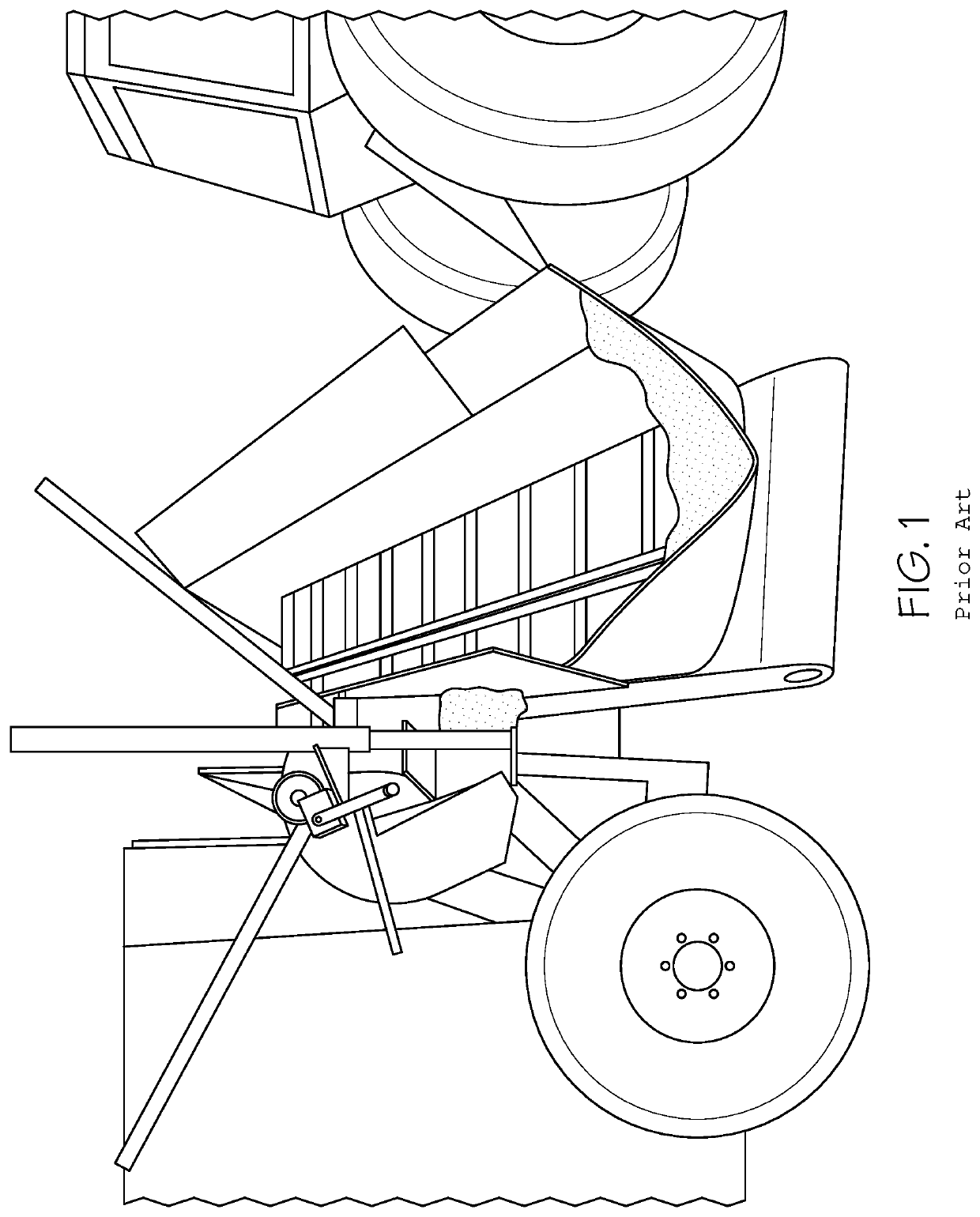
[0026]FIG. 1 shows a conventional forage bagger with the feeding mechanism for inserting material into the machine, and the expandable bag the material is compacted into.

[0027]FIG. 2 is a view of the inventive turbo auger, shown generally at 10 and prior to installation in the forage bagger system, which improves the forage bagger machine, as discussed above.

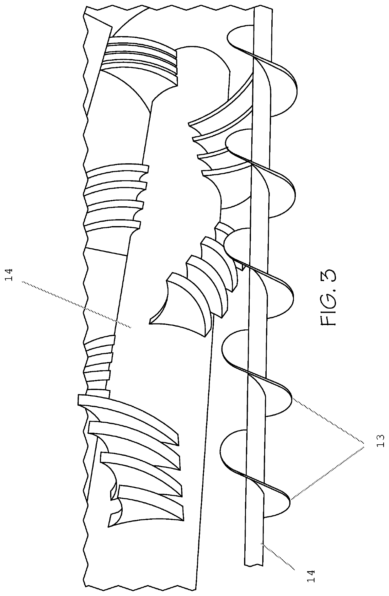
[0028]FIG. 3 is a view of the inventive turbo auger installed in the forage bagger machine (hopper not shown). Testing showed that the best position for the auger 10 is one inch above the floor of the mach...


PUM


Abstract

A compacting machine of the type having a compaction rotor, the improvement being a rotating auger positioned before the compaction rotor, to spread material to be compacted along an entire front of the compaction rotor.

Description

CROSS-REFERENCE TO RELATED APPLICATIONS[0001]This application claims priority to provisional patent application 62 / 977,581, filed Feb. 17, 2020.STATEMENT REGARDING FEDERALLY SPONSORED RESEARCH[0002]Not ApplicableFIELD OF THE INVENTION[0003]The invention relates to an auger which improves the feeding of a forage bagger machine.BACKGROUND OF THE INVENTION[0004]A forage bagger is an agriculture piece of farm equipment used to compact silage and grains with a rotating compaction cylinder (rotor) in a horizontally expandable bag. An example of a forage bagger is the G6000 AG-BAG machine. In the commercially available forage bagger machines, the materials to be compacted are conveyed to one or two spots or positions, feeding the rotor. This is undesirable because it not only feeds the compaction rotor unevenly but also materials can bridge up by sticking to the area opposing the rotor where the compaction process begins.BRIEF SUMMARY OF THE INVENTION[0005]The invention is a rotating auger...

Claims


Application Information

Patent Timeline
Patent Type & Authority Applications(United States)
IPC IPC(8): B30B9/30A01F25/14
CPCB30B9/301A01F2025/145A01F25/14
Inventor YAGER, CRAIG
Owner YAGER CRAIG
Learn More