Filter Element with a Receiving Chamber Containing a Drying Agent, and Fluid Filter

Pending Publication Date: 2021-08-19
MANN HUMMEL GMBH
View PDF1 Cites 0 Cited by
  • Summary
  • Abstract
  • Description
  • Claims
  • Application Information

AI Technical Summary

Benefits of technology

The patent describes a filter element that includes a receiving chamber for a drying agent. The receiving chamber is delimited by a wall through which the fluid can flow. The drying agent is permanently retained in the receiving chamber and helps remove water from the fluid as it flows through the chamber. The filter element and the receiving chamber are non-detachably connected, making servicing easier. The filter element can be easily replaced when the drying agent is no longer effective. The receiving chamber can be positioned inside or outside the filter medium, depending on the needs. The length of the filter element along its longitudinal axis is minimized by the non-detachable connection between the filter medium and the receiving chamber. The technical effects of the invention include improved drying of the fluid, reduced corrosion, prevention of microbial growth, and reduced clogging of the filter.

Problems solved by technology

The water in the fluid can cause undesirable effects such as, for example, corrosion of fluid-conducting components of the system, an increase or decrease of the electrical conductivity of the fluid, and / or reduction of the service life of the fluid, i.e., a shortening of service intervals.
At low temperatures, ice crystals may form that block the system.

Method used


Image

  • Filter Element with a Receiving Chamber Containing a Drying Agent, and Fluid Filter
  • Filter Element with a Receiving Chamber Containing a Drying Agent, and Fluid Filter
  • Filter Element with a Receiving Chamber Containing a Drying Agent, and Fluid Filter

Examples


fourth embodiment

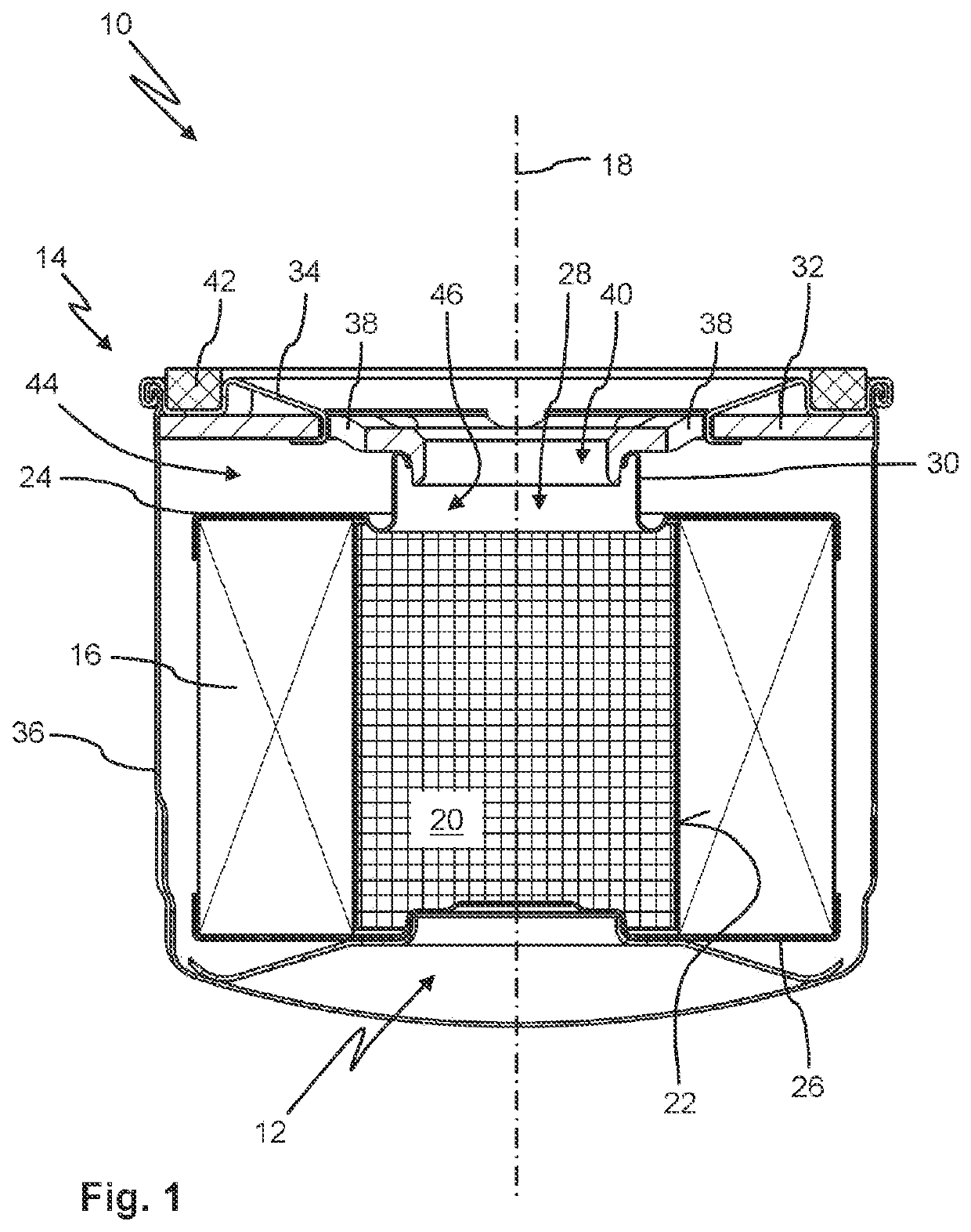
[0075]FIG. 4 shows a fluid filter 10. The fluid filter 10 comprises a filter element 12 and a filter housing 14. The filter element 12 is arranged in the filter housing 14.

[0076]The filter element 12 comprises a filter medium 16. The filter medium 16 surrounds a longitudinal axis 18 of the filter element 12 in a ring shape. The filter medium 16 is embodied here folded in a star shape. The filter medium 16 can be flowed through in radial direction in relation to the longitudinal axis 18 from the exterior to the interior by a fluid.

[0077]The filter element 12 comprises a receiving chamber 20. A drying agent, not illustrated in detail, is arranged in the receiving chamber 20. The drying agent is here a zeolite molecular sieve. The receiving chamber 20 is arranged in axial direction along the longitudinal axis 18 above the ring-shaped filter medium 16. Here, the receiving chamber 20 adjoins in axial direction immediately the filter medium 16. The receiving chamber 20 and the filter medi...

fifth embodiment

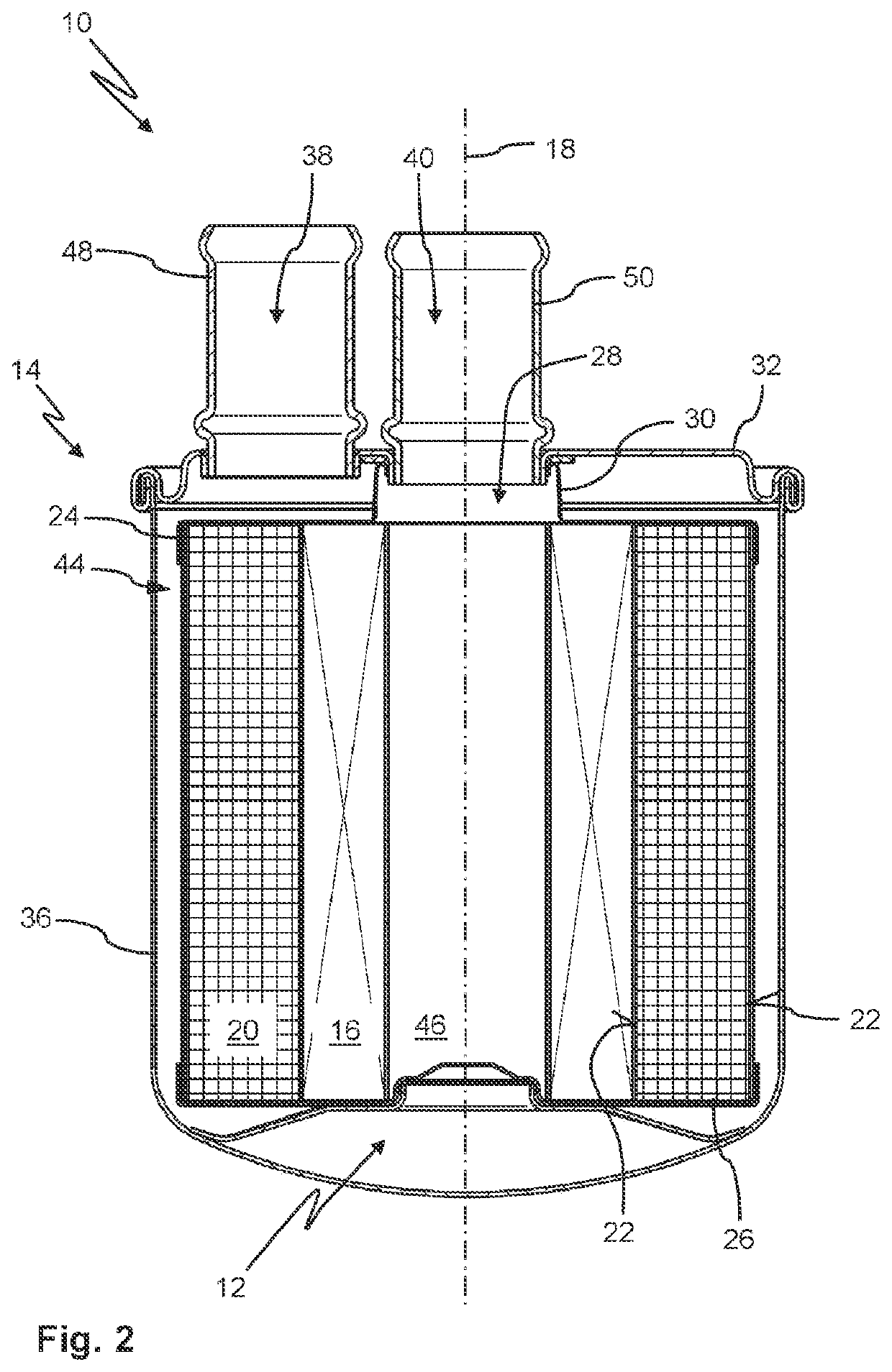
[0091]FIG. 5 shows a fluid filter 10 in a The fluid filter 10 comprises a filter element 12 and a filter housing 14. The filter element 12 is arranged in the filter housing 14.

[0092]The filter element 12 comprises a filter medium 16. The filter medium 16 surrounds a longitudinal axis 18 of the filter element 12 in a ring shape. The filter medium 16 is embodied folded in a star shape here. The filter medium 16 can be flowed through radially in relation to the longitudinal axis 18 from the exterior to the interior by a fluid.

[0093]The filter element 12 comprises a receiving chamber 20. The drying agent, not illustrated in detail, is arranged in the receiving chamber 20. The drying agent is here a silica gel. The receiving chamber 20 is arranged radially inside of the ring-shaped filter medium 16. The receiving chamber 20 and the filter medium 16 extend along the longitudinal axis 18 across the same length. In particular, the receiving chamber 20 and the filter medium 16 end at the en...

sixth embodiment

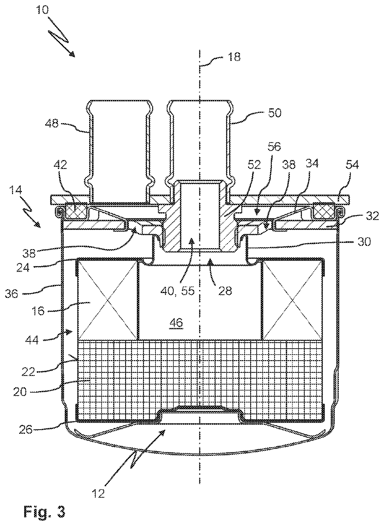
[0099]FIG. 6 shows a fluid filter 10 in a The fluid filter 10 comprises a filter element 12 and a filter housing 14. The filter element 12 is arranged in the filter housing 14.

[0100]The filter element 12 comprises a filter medium 16. The filter medium 16 surrounds a longitudinal axis 18 of the filter element 12 in a ring shape. The filter medium 16 is embodied here in a wound configuration. The filter medium 16 can be flowed through radially in relation to the longitudinal axis 18 from the exterior to the interior by a fluid.

[0101]The filter element 12 comprises a receiving chamber 20. A drying agent, not illustrated in detail, is arranged in the receiving chamber 20. The drying agent is here a zeolite molecular sieve. The receiving chamber 20 is arranged radially outside of the ring-shaped filter medium 16. The receiving chamber 20 and the filter medium 16 extend along the longitudinal axis 18 about the same length. In particular, the receiving chamber 20 and the filter medium 16 ...


PUM

PropertyMeasurementUnit
Pore sizeaaaaaaaaaa
Pressureaaaaaaaaaa
Diameteraaaaaaaaaa

Abstract

A filter element for filtering a liquid has a filter medium that surrounds a longitudinal axis of the filter element in a ring shape and can be flowed through by the liquid in a radial direction in relation to the longitudinal axis. A flow-through receiving chamber is provided that is delimited, at least in sections thereof, by a wall that can be flowed through by the liquid, wherein the receiving chamber contains a drying agent for removal of water from the liquid. The filter medium and the receiving chamber containing the drying agent are non-detachably connected to each other. A fluid filter with a filter housing in which such a filter element is arranged is provided. The filter element is arranged in the filter housing such that, in operation of the fluid filter, both filter medium and receiving chamber containing the drying agent are flowed through by the liquid.

Description

CROSS-REFERENCE TO RELATED APPLICATIONS[0001]This application is a continuation application of international application No. PCT / EP2019 / 072004 having an international filing date of 16 Aug. 2019 and designating the United States, the international application claiming a priority date of 11 Sep. 2018 based on prior filed German patent application No. 10 2018 122 079.0, the entire contents of the aforesaid international application and the aforesaid German patent application being incorporated herein by reference.TECHNICAL FIELD[0002]The invention concerns a filter element for filtering a fluid, in particular oil, with a receiving chamber which, at least in sections thereof, is delimited by a wall through which the fluid can flow and in which a drying agent for removal of water from the fluid is received. Moreover, the invention concerns a fluid filter with such a filter element.BACKGROUND OF THE INVENTION[0003]In fluid-conducting systems, it may happen that water collects in the flui...

Claims


Application Information

Patent Timeline
IPC IPC(8): B01D35/153B01D35/16B01D29/21
CPCB01D35/153B01D29/21B01D35/16B01D27/148B01D27/144B01D37/025
Inventor PANZER, MARIUSTRAUT, ALEXANDER
Owner MANN HUMMEL GMBH
Why Eureka
Try Eureka