Determination of gain characteristics of a circularly-polarized antenna

a circularly polarized antenna and gain characteristic technology, applied in the direction of polarised antenna unit combination, non-resonant long antenna, instruments, etc., can solve the problems of difficult measurement of circularly polarized antenna gain, difficult to meet the requirements of high frequency operation, and complicated set-up of conventional methods

Active Publication Date: 2021-08-12
CITY UNIVERSITY OF HONG KONG
View PDF0 Cites 0 Cited by
  • Summary
  • Abstract
  • Description
  • Claims
  • Application Information

AI Technical Summary

Benefits of technology

The invention provides a method for determining the gain characteristics of a circularly-polarized antenna by measuring the forward gain between a circularly-polarized antenna probe and a linearly-polarized standard-gain antenna. This method includes measuring the amplitude of the forward gain between the two antennas and the cross-polarization level of the two antennas. By measuring the cross-polarization level, the method can account for the effect of cross-polarization on the measured gain. The method can be used to determine the left-hand and right-hand circularly-polarized gains of the antenna. The invention provides an improved system for determining the gain characteristics of a circularly-polarized antenna.

Problems solved by technology

Conventional methods for measuring circularly-polarized gain(s) of circularly-polarized antenna require complicated set-up and relies heavily on phase information.
These conventional methods may not be suitable for high frequency operations.
For example, at high frequency operations such as at millimeter-wave and terahertz ranges, the gains of circularly-polarized antenna are difficult to measure because of the relatively short wavelength and the relatively high sensitivity to misalignment error.
Also, at millimeter-wave and terahertz ranges, the frequency extenders required for measurement are bulky (hence difficult to manipulate) and are delicate (hence prone to be damaged when moved or rotated).
Furthermore, existing circularly-polarized standard-gain horns usually provide a working bandwidth of less than 10%.
This further complicates the measurement, especially for broadband circularly-polarized antennas.

Method used


Image

  • Determination of gain characteristics of a circularly-polarized antenna
  • Determination of gain characteristics of a circularly-polarized antenna
  • Determination of gain characteristics of a circularly-polarized antenna

Examples


Embodiment Construction

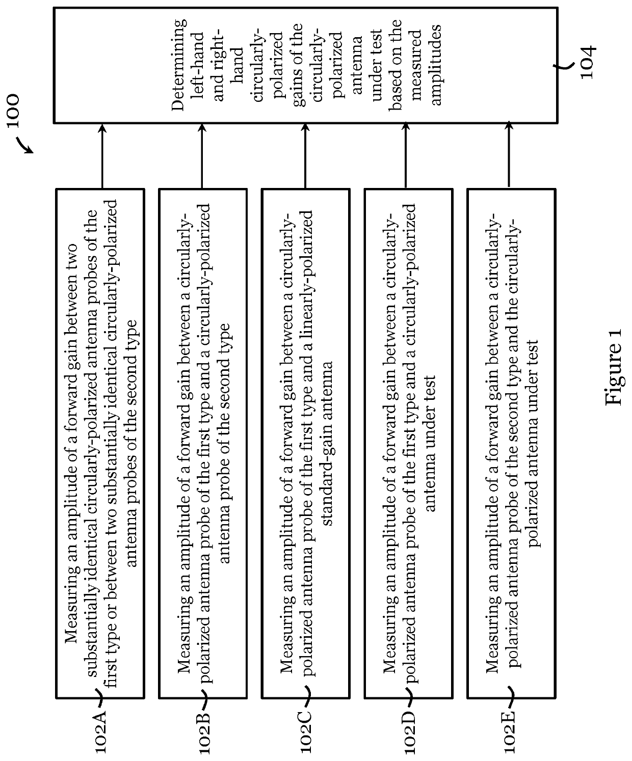
[0073]FIG. 1 illustrates a method 100 for determining gain characteristics of a circularly-polarized antenna in one embodiment of the invention. The circularly-polarized antenna under test in this method 100 is arranged for operation in millimeter-wave and terahertz ranges.

[0074]The method 100 includes, in step 102A, measuring an amplitude of a forward gain (e.g., forward voltage gain) between two substantially identical circularly-polarized antenna probes of the first type or between two substantially identical circularly-polarized antenna probes of the second type. In this example, the circularly-polarized antenna probe of the first type is a left-hand circularly-polarized antenna probe, and the circularly-polarized antenna probe of the second type is a right-hand circularly-polarized antenna probe. The measurement in step 102A includes connecting two substantially identical circularly-polarized antenna probes of the first type (or of the second type) to a measurement device, posi...


PUM


Abstract

System and method for determining gain characteristics of a circularly-polarized antenna. The method includes receiving a measured first amplitude of a forward gain between a circularly-polarized antenna probe of a first type and a linearly-polarized standard-gain antenna, a measured second amplitude of a forward gain between a circularly-polarized antenna probe of a first type and a circularly-polarized antenna under test, and a measured third amplitude of a forward gain between a circularly-polarized antenna probe of a second type and the circularly-polarized antenna under test. The method also includes determining a left-hand circularly-polarized gain and a right-hand circularly-polarized gain of the circularly-polarized antenna under test based on the measured first amplitude, the measured second amplitude, the measured third amplitude, and a cross-polarization level of the circularly-polarized antenna probes of the first and second types. The determination may be performed using one or more processors.

Description

TECHNICAL FIELD[0001]The invention relates to determination of gain characteristics of a circularly-polarized antenna.BACKGROUND[0002]Circularly-polarized gain(s) of a circularly-polarized antenna can be measured to evaluate the performance or properties of the antenna. Conventional methods for measuring circularly-polarized gain(s) of circularly-polarized antenna require complicated set-up and relies heavily on phase information. These conventional methods may not be suitable for high frequency operations. For example, at high frequency operations such as at millimeter-wave and terahertz ranges, the gains of circularly-polarized antenna are difficult to measure because of the relatively short wavelength and the relatively high sensitivity to misalignment error. Also, at millimeter-wave and terahertz ranges, the frequency extenders required for measurement are bulky (hence difficult to manipulate) and are delicate (hence prone to be damaged when moved or rotated). Furthermore, exist...

Claims


Application Information

Patent Timeline
IPC IPC(8): G01R29/08H01Q21/24H01Q11/06
CPCG01R29/0878H01Q11/06H01Q21/24G01R29/10
Inventor DING, CHENLUK, KWAI-MAN
Owner CITY UNIVERSITY OF HONG KONG
Why Eureka
Try Eureka