Eureka AIR delivers breakthrough ideas for toughest innovation challenges, trusted by R&D personnel around the world.

Wire harness wire end protection method

Pending Publication Date: 2021-07-01
FURUKAWA ELECTRIC CO LTD +3
View PDF0 Cites 1 Cited by
  • Summary
  • Abstract
  • Description
  • Claims
  • Application Information

AI Technical Summary

Benefits of technology

The present invention provides a simple protective member that can be used to protect bended sections of electric wires. This versatility is achieved through the use of a protective member that can be adapted to various needs and situations.

Problems solved by technology

This undesirably increases the number of types of covers and the number of dies or molds needed for producing the covers.
However, in the case where this structure is applied to a so-called horizontal connector, it is difficult to realize both of covering of the bent portion of the electric wires and covering of an end portion of the connector with the sheet member.

Method used


Image

  • Wire harness wire end protection method
  • Wire harness wire end protection method
  • Wire harness wire end protection method

Examples


Embodiment Construction

[0026]Hereinafter, an embodiment in which the present invention is carried out will be described with reference to the drawings.

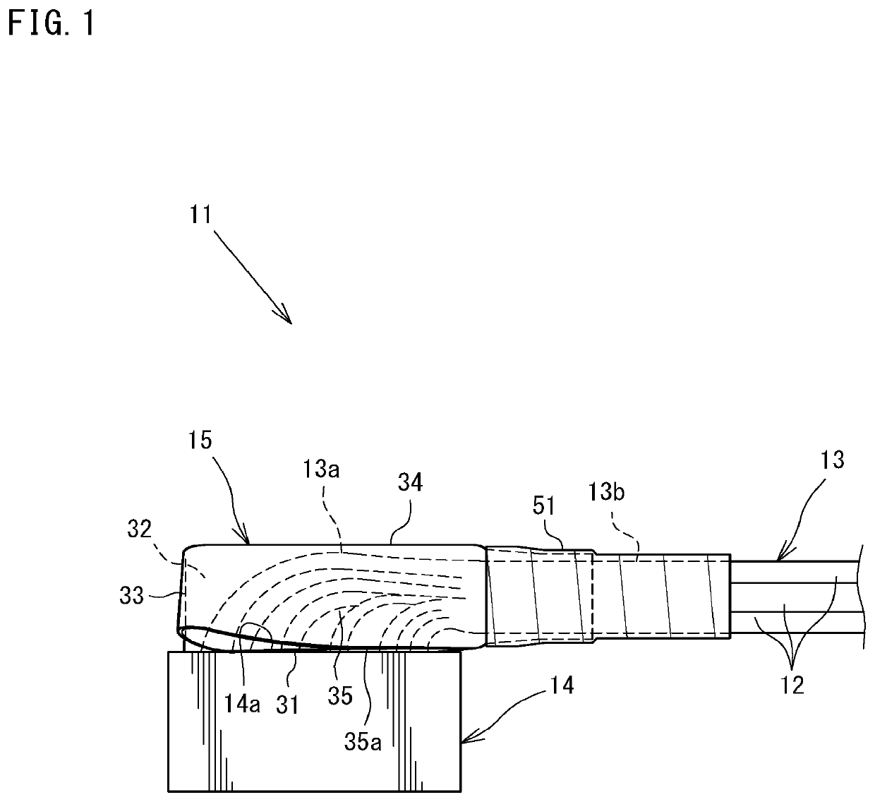
[0027]FIG. 1 is a side view of an example of wire end of a wire harness 11, to which a wire harness wire end protection method in this embodiment is applicable. The wire harness 11 includes a wire bundle 13 including a plurality of electric wires 12 assembled together, and a connector 14, to which a terminal (not shown) connected with the wire end of the electric wires 12 is inserted and held. The wire end of the wire bundle 13 facing the connector 14 is bent to form a bent portion 13a in the vicinity of a wire lead-out surface 14a of the connector 14.

[0028]The bent portion 13a is formed in the case where the wire bundle 13 is led out in a horizontal direction in correspondence with the wiring of the wire harness 11 or in the case where if the electric wires 12 are led out linearly from the wire lead-out surface 14a of the connector 14, namely, in a directi...


PUM


Abstract

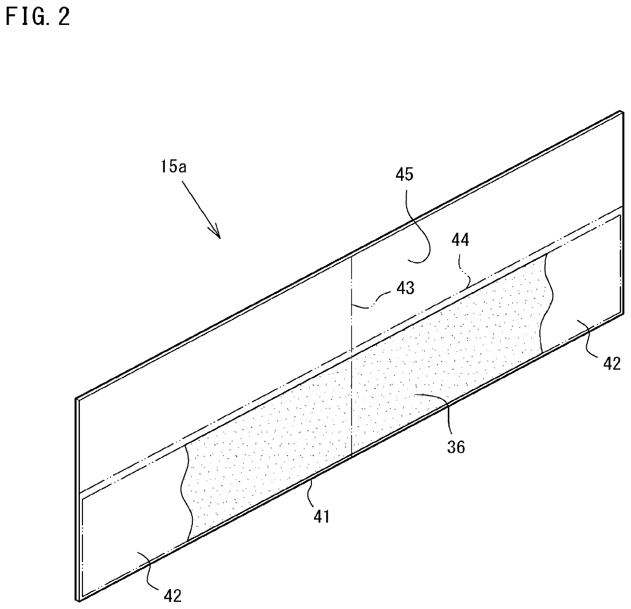
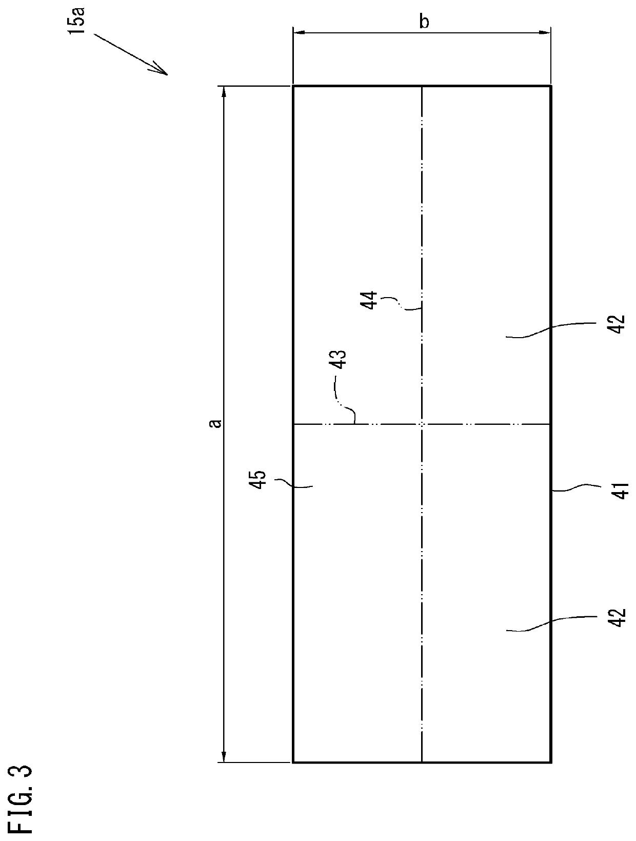
A bent portion of electric wires is protected at a high versatility by a protective member having a simple shape. A wire end of a wire harness 11 is protected. The wire harness 11 includes a wire bundle 13 and a connector 14 connected therewith. The wire bundle 13 includes the wire end, and the wire end includes a bent portion 13a and faces the connector 14. First, a sheet member 15a is folded perpendicularly to a wire lead-out surface 14a of the connector 14, thereby forming, concurrently, counter sides 31 facing the wire lead-out surface 14a, side surface covering portions, and a tip end protection portion 33. Next, the side surface covering portions are folded along a top protection portion formation portion 44, thereby forming, concurrently, side surface protection portions 32, a top protection portion 34 and an extending portion 35. Next, a wire end protection portion 15 is secured, with a pressure-sensitive adhesive tape or the like, to a wire bundle 13 portion while the relative position of the counter sides 31 with respect to the wire lead-out surface 14a is maintained. The wire end protection portion 15 is secured only to the wire bundle 13 portion, but is not secured to the connector 14.

Description

TECHNICAL FIELD[0001]The present invention relates to a technology for protecting a wire end of a wire harness, and more specifically, to protection of a base portion for a connector of a wire harness, the wire harness including a wire bundle and the connector connected therewith, the wire bundle including the wire end, the wire end including a bent portion.BACKGROUND ART[0002]In a connector in which a wire bundle is bent in the vicinity of a wire lead-out portion thereof, namely, in a so-called horizontal connector, the bent portion of the wire bundle is provided with a cover in order to protect electric wires against dust or the like and also in order to restrict the bending shape or the orientation of the wire bundle.[0003]One conventional example of such a cover is disclosed in Patent Document 1. The cover disclosed in Patent Document 1 includes a portion to be fit into the connector, a portion accommodating the bent portion, and a portion from which the electric wires are led o...

Claims


Application Information

Patent Timeline
IPC IPC(8): H01B13/012H02G15/02H02G3/04H01R9/22
CPCH01B13/01209H02G15/02B60R16/0215H01R9/223H02G3/0406H01B13/012H02G15/04H01R13/562H01R13/5205H01R24/20H01R2107/00H01B13/01263Y10T29/49117
Inventor KASUGAI, YUMIKOFUJIMURA, TAKUYATAKEUCHI, TOMOYA
Owner FURUKAWA ELECTRIC CO LTD
Why Eureka
Eureka Blog
Learn More