Distance measurement system for a vehicle

a technology for distance measurement and vehicles, applied in lifting devices, safety devices for lifting equipment, instruments, etc., can solve problems such as inability to detect control panels, erroneous measurements, and movement of work cages

Pending Publication Date: 2021-06-17
MOBA MOBILE AUTOMATION
View PDF16 Cites 0 Cited by
  • Summary
  • Abstract
  • Description
  • Claims
  • Application Information

AI Technical Summary

Benefits of technology

[0018]According to embodiments, the signal deflection apparatus is mounted on the measurement unit or on the measurement module in a releasable manner, in particular releasable without any tools. The signal deflection apparatus can, for example, be clicked (click connection), clamped, stuck or mounted by means of Velcro connection or the same on / to the measurement unit or the measurement module. This is particularly advantageous when the signal deflection apparatus is defect as the same can then be exchanged easily and possibly without any tools. However, it is also possible that the signal deflection apparatus is screwed onto the measurement unit or the measurement module.
[0019]According to embodiments, the signal deflection apparatus includes a holder and a reflector unit that are connected to each other in a releasable manner, in particular releasable without any tools. The holder can also be mounted on the measurement unit or on the measurement module in a releasable manner, however, a fixed mounting on the measurement module or a holder mechanism preformed at the housing of the measurement module is possible, i.e. a holder mechanism integrated in the housing of the measurement module. The reflector unit including the reflector surface is also arranged on the holder in a releasable manner. The reflector unit can, for example, be clicked (click connection), clamped, stuck or mounted by means of a Velcro connection or the same. If the reflector unit is, for example, defect, the same can advantageously be released from the holder and exchanged easily.
[0020]According to embodiments, the reflector unit is arranged on the holder in a slidable manner, in particular slidable to the side. Thereby, the measurements direction of the distance measurement can be changed easily or the measurement direction of the measurement module or the measurement unit can be changed and thereby be adapted to the conditions of the vehicle or the machine. If, for example, a measurement module having two measurement units is to be used on the vehicle or the machine for two different measurement directions, for example, in the first measurement unit, the reflector unit can be slid directly in front of the sensor unit, such that the signal emitted by the sensor unit of the first measurement unit is deflected in the direction of the object or the obstacle, whereas in the second measurement unit the reflector unit is slid towards the side, such that the signal emitted by the sensor unit of the second measurement unit is not deflected (and accordingly has a different measurement direction).
[0021]According to embodiments, the holder comprises a lock for locking the reflector unit and / or the reflector unit 52 comprises a lock for locking the same. Thereby, automatic release of the reflector unit during operation of the vehicle or the machine is advantageously prevented. Advantageously, the lock can be operated easily and quickly with the touch of a finger, such that the reflector unit can be released from the holder and exchanged easily. Here, the lock can be arranged on the holder and / or on the reflector unit.
[0026]According to embodiments, the measurement units of a measurement module have a common evaluation unit. If, for example two or three measurement units are arranged in or on a measurement module, it is possible that the sensor units are electrically connected to a common evaluation unit. Thereby, the measurement module as a whole becomes more cost-effective since electronic components can be saved. However, it is also possible that more than two or three measurement units are electrically connected to a common evaluation unit. It is advantageous and cost-effective when all measurement units arranged in or on a measurement module are electrically connected to the same evaluation unit of a measurement module.
[0028]According to embodiments, the distance measurement system includes several measurement modules that can be connected to one another by means of an electric cable connection or a wireless connection. Measurement modules can be arranged by means of an electric cable connection or a wireless connection in a cascaded manner in a distance measurement system, i.e. the same can be connected in series or can be connected to one another such that the distance measurement system consists of two or several measurement modules. The measurement modules or the measurement units or the evaluation units arranged in the measurement units can communicate to one another and can output distance values or pass them on to a control, for example to a vehicle or a machine control, for example by means of a field bus system (CAN, LIN or the same). For this, advantageously, the field bus system of the distance measurement system is electrically connected to the field bus system of the machine or the vehicle. This cascading is advantageous since the distance measurement system can be designed or configured with a very flexible structure or design. The same can be individually adapted to different vehicles or machines, i.e. such that, for example, the number of measurement modules or the length of the cable connections between the individual measurement modules can be configured freely and very flexibly.

Problems solved by technology

It is a disadvantage of the known system that depending on the arrangement of the control panel in the work cage, not all objects in the surroundings of the work cage are detected and hence collisions with obstacles that have not been detected can result when the work cage is moving.
Further, erroneous measurements can occur, in particular with transmitters and receivers oriented towards the top as, for example, rainwater may not run off but remains on the sensor heads.
This can have the effect that a person leaning in the direction of the control panel may not be detected or may not be detected correctly and might get caught.

Method used


Image

  • Distance measurement system for a vehicle
  • Distance measurement system for a vehicle
  • Distance measurement system for a vehicle

Examples


Embodiment Construction

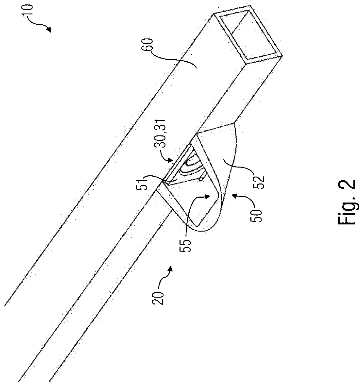
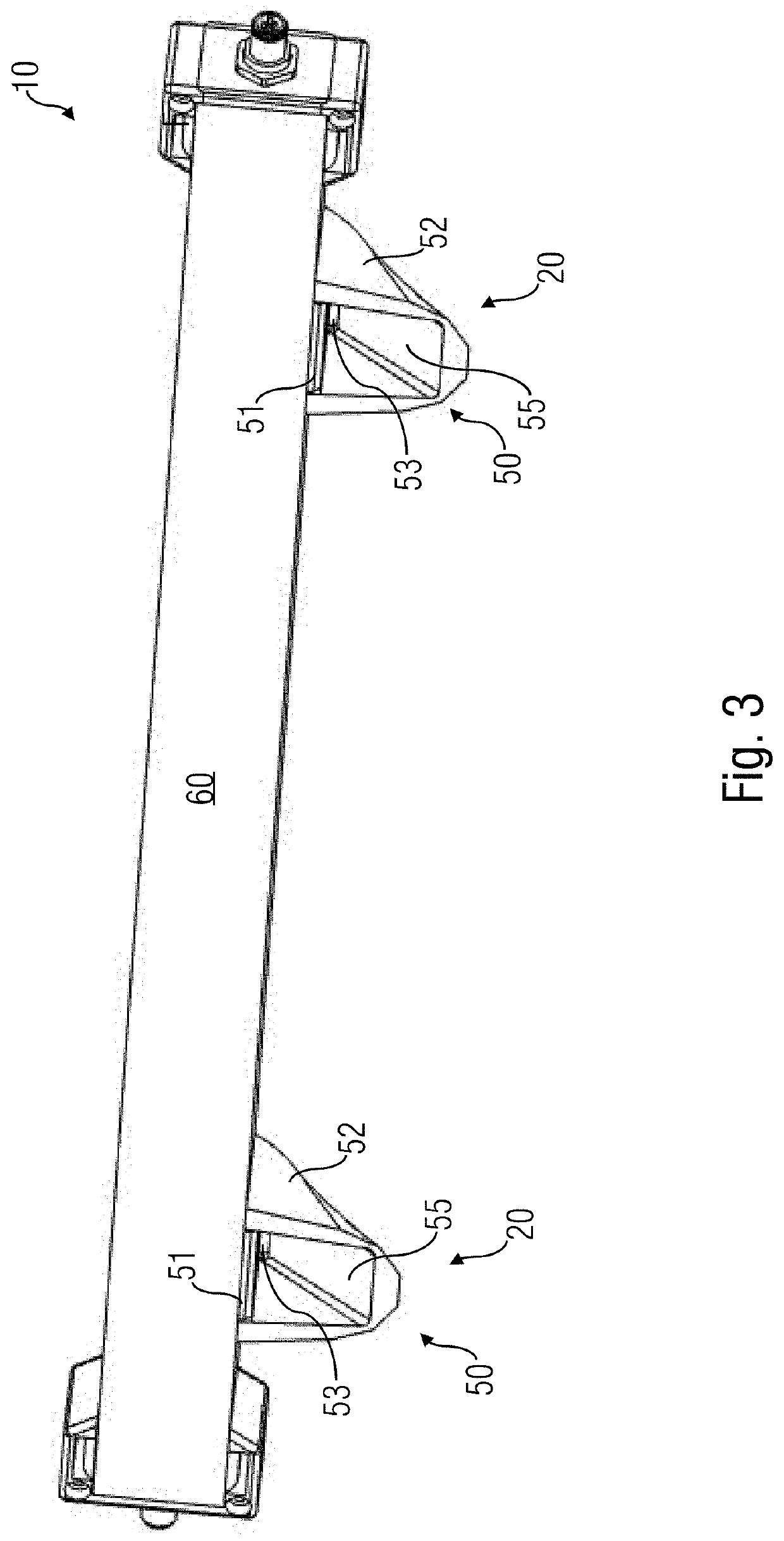
[0040]Before embodiments of the present invention will be discussed in more detail below based on the figures, it should be noted that equal elements are provided with the same reference numbers, such that the description of the same is inter-applicable or inter-exchangeable. In distance measurements, the distance to the reflector surface 55 that deflects the signal S11 emitted by the sensor unit 30 in the direction of the object 70 or the obstacle 70 has to be incorporated in the calculation. Since this distance value should be known when designing the distance measurement system 10, the value can, for example, be stored (for example saved) as a constant in the evaluation means 40 or the sensor unit 30.

[0041]FIGS. 1a and 1b show a distance measurement system 10, each in a schematic illustration, to explain the basic mode of operation of the distance measurement. The distance measurement system 10 comprises a measurement unit 20 for non-contact determination of a distance to an obje...


PUM


Abstract

Distance measurement system for a vehicle, wherein the distance measurement system includes a measurement unit for non-contact determination of a distance to an object and the measurement unit includes: a sensor unit configured to emit a signal and to receive a signal reflected by the object; an evaluation unit determining a distance between the measurement unit and the object from the signals emitted and received by the sensor unit; and a signal deflection apparatus arranged in the area of the sensor unit with a reflector surface deflecting the signal emitted by the sensor unit in a direction deviating from the propagation direction of the signal, in particular at an essentially right angle to the propagation direction of the signal, in the direction of the object.

Description

CROSS-REFERENCE TO RELATED APPLICATIONS[0001]This application claims priority from German Patent Application No. 102019219619.5, which was filed on Dec. 13, 2019, and is incorporated herein in its entirety by reference.[0002]Embodiments of the present invention relate to a distance measurement system as well as to a vehicle having a distance measurement system. Generally, the invention is in the field of vehicles, such as mobile construction or work machines, elevating work platforms, fire engine turntable ladders or the same.BACKGROUND OF THE INVENTION[0003]From WO 2017 / 178737 A1, a control panel for an elevating platform with protection against crushing of the operator is known. The elevating work platform includes a work cage with rails provided thereon, wherein a control panel for controlling movements of the elevating work platform is arranged on the rails. A system by which it can be determined whether the control panel is mounted on the rails, whether a person is in the work ...

Claims


Application Information

Patent Timeline
Patent Type & Authority Applications(United States)
IPC IPC(8): G01S13/931G01S13/08
CPCG01S13/931G01S13/08G01S17/08G01S17/931A62C27/00B66F17/006B66F11/044G01S7/027
Inventor SCHMIDT, THOMASGEMMER, MARTIN JANHORN, ALFONS
Owner MOBA MOBILE AUTOMATION
Why Eureka
Try Eureka