Methods and apparatus for use with cochlear implants having magnet apparatus with magnetic material particles

Active Publication Date: 2021-05-27
ADVANCED BIONICS AG
View PDF0 Cites 4 Cited by
  • Summary
  • Abstract
  • Description
  • Claims
  • Application Information

AI Technical Summary

Problems solved by technology

If, on the other hand, the force is too high, the pressure on the skin flap can result is discomfort and tissue necrosis.
Some conventional cochlear implants are not compatible with magnetic resonance imaging (“MRI”) systems.
The misalignment of the interacting magnetic fields M and B is problematic for a number of reasons.
Reorientation of the magnet 26 can place significant stress on the dermis (or “skin”), which cause significant pain.
The pres

Method used


Image

  • Methods and apparatus for use with cochlear implants having magnet apparatus with magnetic material particles
  • Methods and apparatus for use with cochlear implants having magnet apparatus with magnetic material particles
  • Methods and apparatus for use with cochlear implants having magnet apparatus with magnetic material particles

Examples


Embodiment Construction

[0056]The following is a detailed description of the best presently known modes of carrying out the inventions. This description is not to be taken in a limiting sense, but is made merely for the purpose of illustrating the general principles of the inventions.

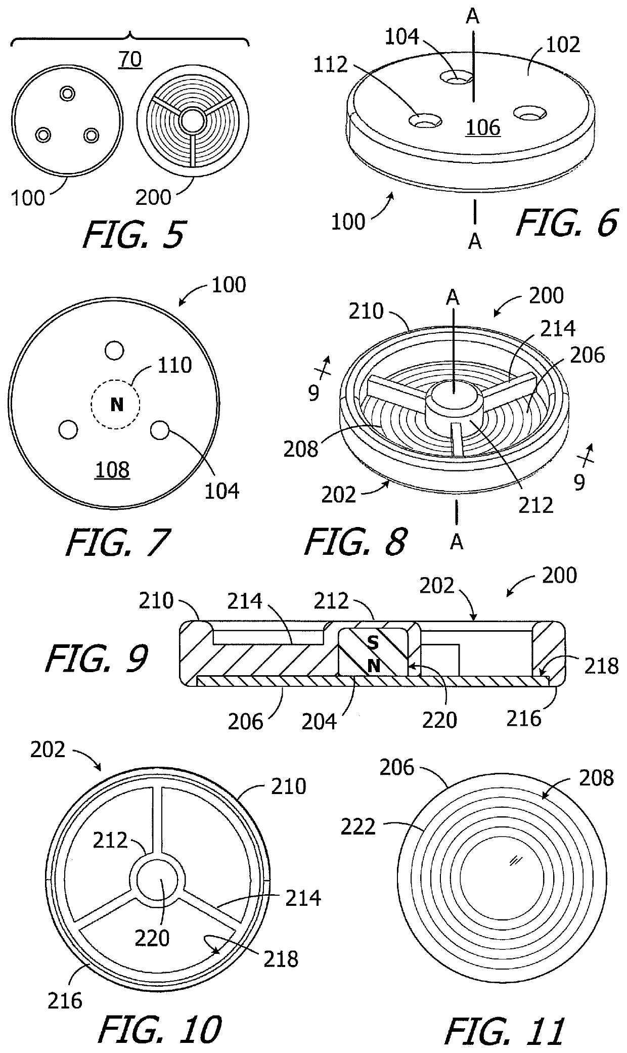
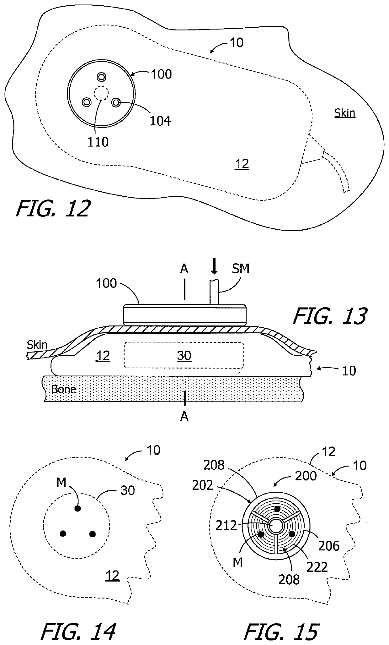
[0057]As illustrated in FIG. 5, one example of a particle alignment indication kit 70 includes a location identification template 100, which is discussed in greater detail below with reference to FIGS. 6 and 7, and an alignment gauge 200, which is discussed in greater detail below with reference to FIGS. 8-11. The particle alignment indication kit 70 may be used, for example, in the manner described below with reference to FIGS. 12-17 to determine whether or not exposure to a relatively strong MRI magnetic field has caused the magnetic material particles in a magnetic material particle-based MRI-compatible magnet apparatus to become misaligned.

[0058]Turning to FIGS. 6 and 7, the exemplary location identification template 100 i...


PUM


Abstract

A particle alignment method in accordance with at least one of the present inventions includes the step of positioning a cochlear implant, which is implanted within a patient's head and which includes a magnet apparatus with a central axis and magnetic material particles, at a location outside of the scanning area of an MRI system, adjacent to the MRI system, and within the MRI magnetic field in such a manner that the central axis of the magnet apparatus is at least substantially parallel to the MRI magnetic field.

Description

BACKGROUND1. Field[0001]The present disclosure relates generally to the implantable portion of implantable cochlear stimulation (or “ICS”) systems.2. Description of the Related Art[0002]ICS systems are used to help the profoundly deaf perceive a sensation of sound by directly exciting the intact auditory nerve with controlled impulses of electrical current. Ambient sound pressure waves are picked up by an externally worn microphone and converted to electrical signals. The electrical signals, in turn, are processed by a sound processor, converted to a pulse sequence having varying pulse widths, rates and / or amplitudes, and transmitted to an implanted receiver circuit of the ICS system. The implanted receiver circuit is connected to an implantable electrode array that has been inserted into the cochlea of the inner ear, and electrical stimulation current is applied to varying electrode combinations to create a perception of sound. The electrode array may, alternatively, be directly in...

Claims


Application Information

Patent Timeline
IPC IPC(8): G01R33/28A61N1/05A61N1/08
CPCG01R33/285G01R33/288A61N1/086A61N1/0541A61B5/70A61B5/055A61N1/36038A61N1/37518
Inventor SMITH, JAMES GEORGE ELCOATELEE, SUNG JINWALTER, JERYLE L.GOMMEL, ULIREED, STEPHANIE M.
Owner ADVANCED BIONICS AG
Why Eureka
Try Eureka