Piston ring and compressor
a piston ring and compressor technology, applied in the direction of machines/engines, mechanical equipment, positive displacement liquid engines, etc., can solve the problems of impaired sealing properties of the piston ring, and achieve the effect of reliable sealing
- Summary
- Abstract
- Description
- Claims
- Application Information
AI Technical Summary
Benefits of technology
Problems solved by technology
Method used
Image

Examples
first embodiment
[0018]
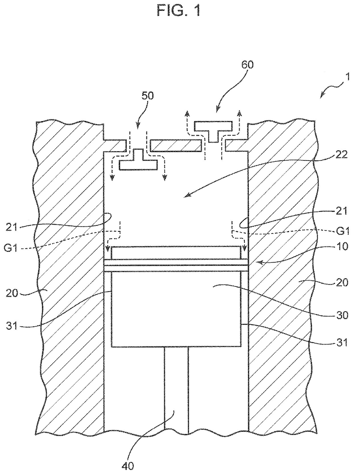
[0019]First, the configuration of a compressor 1 according to the first embodiment of the present invention will be described with reference to FIG. 1. FIG. 1 is a cross sectional view schematically showing the configuration of the vicinity of a piston 30 in the compressor 1. It is to be noted that FIG. 1 shows only some components of the compressor 1, and the compressor 1 can be provided with any other components not shown in FIG. 1.
[0020]The compressor 1 is a reciprocating compressor that pressurizes gas sucked into a cylinder 20 through a suction valve 50 by the piston 30 and discharges the pressurized gas through a discharge valve 60. As shown in FIG. 1, the compressor 1 is mainly provided with the cylinder 20, the piston 30, a piston rod 40, and a piston ring 10. Although not shown, the compressor 1 is further provided with a crankshaft, a connecting rod, and a crosshead.
[0021]The compressor 1 in the present embodiment is used in a hydrogen station, which is a facility th...
second embodiment
[0060]Next, a piston ring 10A according to the second embodiment of the present invention will be described with reference to FIG. 5. While the piston ring 10A according to the second embodiment has basically the configuration similar to that of the piston ring 10 according to the first embodiment and achieves the effects similar thereto, there is a difference in that the second ring portion 12 is divided into a plurality of ring elements. Hereinafter, only the difference from the piston ring 10 according to the first embodiment will be described.
[0061]FIG. 5 schematically shows the configuration of the piston ring 10A in plan view from the axial direction. As shown in FIG. 5, the second ring portion 12 includes a plurality of (two in the present embodiment) circumferentially divided second ring elements 71. Each of the second ring elements 71 is a component having an arc shape extending along the circumferential direction of the second ring portion 12, and has an arc length slightl...
third embodiment
[0066]Next, a piston ring 10B according to the third embodiment of the present invention will be described with reference to FIG. 6. While the piston ring 10B according to the third embodiment has basically the configuration similar to that of the piston ring 10A (FIG. 5) according to the second embodiment and achieves the effects similar thereto, there is a difference in that the first ring portion 11 is divided into a plurality of ring elements. Hereinafter, only the difference from the piston ring 10A according to the second embodiment will be described.
[0067]FIG. 6 schematically shows the configuration of the piston ring 10B in plan view from the axial direction. As shown in FIG. 6, the first ring portion 11 includes a plurality of (two in the present embodiment) circumferentially divided first ring elements 72. Each of the first ring elements 72 is a component having an arc shape extending along the circumferential direction of the first ring portion 11, and has an arc length s...
PUM
| Property | Measurement | Unit |
|---|---|---|
| pressure | aaaaa | aaaaa |
| pressure | aaaaa | aaaaa |
| axial length | aaaaa | aaaaa |
Abstract
Description
Claims
Application Information
 - R&D
- Intellectual Property
- Life Sciences
- Materials
- Tech Scout
- Unparalleled Data Quality
- Higher Quality Content
- 60% Fewer Hallucinations
Browse by: Latest US Patents, China's latest patents, Technical Efficacy Thesaurus, Application Domain, Technology Topic, Popular Technical Reports.
© 2025 PatSnap. All rights reserved.Legal|Privacy policy|Modern Slavery Act Transparency Statement|Sitemap|About US| Contact US: help@patsnap.com