
Automatic access control devices and clusters thereof

a technology of automatic access control and access control device, which is applied in the direction of power supply, door/window fitting, construction, etc., can solve the problem of unidirectional flow through the device, and achieve the effect of maximizing the throughput rate of the access control devi

Active Publication Date: 2021-05-27
OSANN JR ROBERT
View PDF0 Cites 1 Cited by
  • Summary
  • Abstract
  • Description
  • Claims
  • Application Information

AI Technical Summary

Benefits of technology

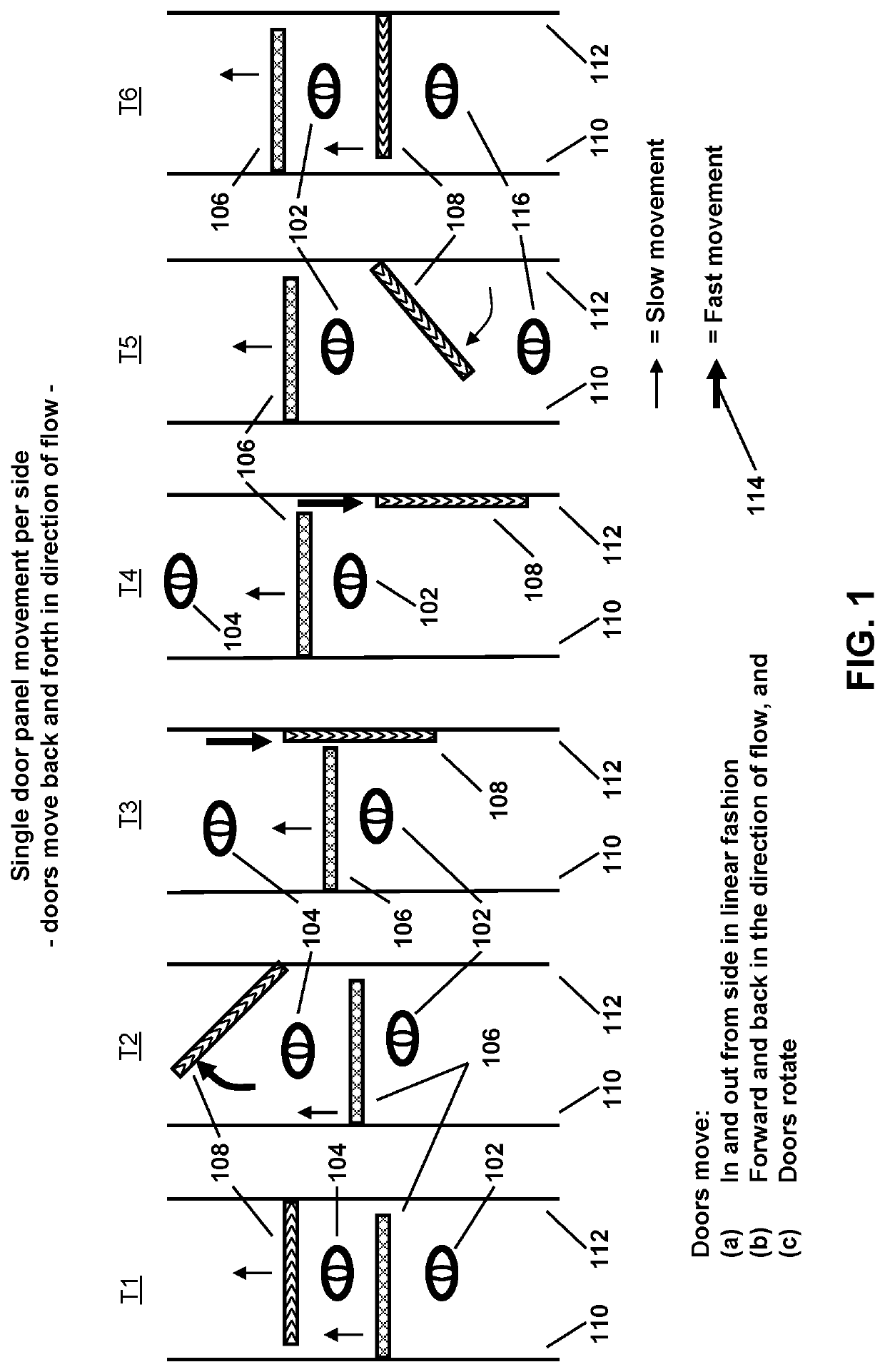
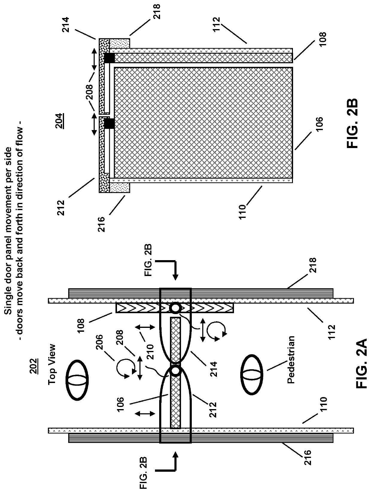
The patent describes an access control device that can automatically adjust its movement to match the speed of individuals passing through it, allowing for maximum throughput. It uses electromechanical means to drive the door panels and proximity sensors to detect and track individuals. The device can also prevent the passage of weapons and can operate unattended for extended periods of time. It includes ducting for controlled airflow and may include additional sliding panels to fill gaps between the door panels and side panels. The moving door panels are suspended from roof panels and are driven by mechanisms incorporated into the moving roof panels, which also provide a top cover to prevent weapon passing.

Problems solved by technology

At any instant in time, the flow through the device is unidirectional.

Method used


Image

  • Automatic access control devices and clusters thereof
  • Automatic access control devices and clusters thereof
  • Automatic access control devices and clusters thereof

Examples


Embodiment Construction

[0087]The invention is illustrated by way of example and not by way of limitation in the figures of the accompanying drawings in which like references indicate similar elements. References to embodiments in this disclosure are not necessarily to the same embodiment, and such references mean at least one. While specific implementations are discussed, it is understood that this is done for illustrative purposes only. A person skilled in the relevant art will recognize that other components and configurations may be used without departing from the scope and spirit of the invention.

[0088]In the following description, numerous specific details are set forth to provide a thorough description of the invention. However, it will be apparent to those skilled in the art that the invention may be practiced without these specific details. In other instances, well-known features have not been described in detail so as not to obscure the invention.

[0089]In accordance with the embodiments of the in...


PUM


Abstract

Electro-mechanical and electronically controlled access devices are described for automatically controlling passage between two areas, and where a plurality of such access control devices may be ganged or clustered to provided additional throughput and directional control, including stacking a plurality of access control devices side by side within a cluster. Each access control device contains multiple rotatable and moveable door panels. The door panels are controlled by various drive mechanisms to enable passage through the device, while ensuring by the use of sensors that door panels avoid touching subjects as they traverse the device. The direction of flow through a device according to these embodiments is electronically controlled and may be changed from time to time. At any instant in time while being traversed, the flow through each device is unidirectional. Multiple devices within a cluster can be directionally controlled according to traffic, demand, time of day, or other factors.

Description

PRIORITY CLAIM[0001]This application claims priority as a continuation of U.S. application Ser. No. 16 / 802,816 filed on Feb. 27, 2020, presently pending, which in turn claimed priority as a continuation of U.S. application Ser. No. 15 / 588,617 filed on May 6, 2017, issued as U.S. Pat. No. 10,590,693 on Mar. 17, 2020, which in turn claimed priority as a continuation of U.S. Ser. No. 14 / 690,245 filed on Apr. 17, 2015, issued as U.S. Pat. No. 9,644,417 on May 9, 2017. U.S. application Ser. No. 14 / 690,245 is a continuation in part of U.S. Ser. No. 14 / 485,705, filed on Sep. 13, 2014, which issued as U.S. Pat. No. 9,010,025 on Apr. 21, 2015. U.S. application Ser. No. 14 / 485,705, in turn, claims priority as a continuation of U.S. patent application Ser. No. 13 / 952,409 filed on Jul. 26, 2013, which issued as U.S. Pat. No. 8,832,997 on Sep. 16, 2014, which in turn claimed priority as a continuation in part of U.S. patent application Ser. No. 12 / 502,997 filed on Jul. 14, 2009, which issued as ...

Claims


Application Information

Patent Timeline
Patent Type & Authority Applications(United States)
IPC IPC(8): E05F15/73E05F17/00E05F15/608E05G5/00E05D15/58E05F15/79E05F15/627E05F15/646E05G5/02E05F15/60
CPCE05F15/73E05F17/002E05F15/608E05G5/003E05D15/58E05F15/00E05F15/627E05F15/646E05G5/02E05F15/60E05F15/79E05F2017/008E05Y2400/82E05Y2900/132E05F2015/765E05F2015/767
Inventor OSANN, JR., ROBERT
Owner OSANN JR ROBERT
Learn More