Bone conduction speaker unit

a speaker unit and bone technology, applied in the direction of transducer casings/cabinets/supports, electrical transducers, electrical apparatus, etc., can solve the problems of sound leakage, increased so-called leakage sound, and higher air conduction sound (sound leakage) from the speaker unit itsel

Inactive Publication Date: 2021-04-29
TEMCO JAPAN
View PDF0 Cites 1 Cited by
  • Summary
  • Abstract
  • Description
  • Claims
  • Application Information

AI Technical Summary

Benefits of technology

[0032]FIG. 6C gives a graph of vibration characteristics for a conventional bone conduction speaker unit, in which the yoke is fixed to an inner bottom face of the casing; and
[0033]FIG. 7 is a longitudinal sectional view giving an example of configuration of conventional bone conduction speaker units.

Problems solved by technology

In case where this bone conduction speaker unit is incorporated in a handset of telephone, there is a possibility that the vibration of a speaker part of the bone conduction speaker unit may cause the housing of the handset to be vibrated, resulting in occurrence of a sound leakage, and a vibrational output sneaking to a microphone, tending to cause howling.
Since the bone conduction speaker unit of such a type has a structure that causes the casing to be vibrated as a whole, it is required that, when the bone conduction speaker unit is incorporated into the handset main body, an appropriate elastic base be interposed between the unit and the main body to absorb the vibration of the speaker, and otherwise, the main body is vibrated, resulting in the so-called leakage sound being increased, which is a drawback of the bone conduction speaker unit of this type.
In addition, the larger the size of the speaker unit, the higher the air conduction sound (sound leakage) from the speaker unit itself will be.
However, the configuration according to this proposal gives a disadvantage that, although the vibration in the medium and high areas can be transmitted with no problem at the time of use in the vibration-absorbable range, the vibration in the low area is absorbed by the elastic base, being attenuated, thereby the low-area characteristics being not be able to be sufficiently secured.
In such a case, if the speaker unit is heavily pressed against the human body in order to cover the low area characteristics, the vibration will not be absorbed by the elastic base portion, resulting in the vibration being transmitted to the main body, and thus the sound leakage is increased.
However, with this bone conduction speaker unit, at the time of non-use, when no pressing force is applied to the elastic cover, a gap is always held between the bottom face of the contact and the top face of the elastic plate, or between the bottom of a larger thickness portion of the elastic cover and the top face of the plate yoke, whereby it is positively prevented that a vibration is inadvertently transmitted to the elastic cover to generate a voice vibration, resulting in occurrence of a sound leakage, and thus it could be the that such bone conduction speaker unit is not intended for improving the vibration characteristics.
As described above, with mobile phones, and the like, which use a conventional bone conduction speaker, the contact is always in tight contact with the plate yoke, thereby, even at the time of non-calling, when the contact is not abutted against a side face of the head, the contact being vibrated to generate a voice vibration, resulting in occurrence of a sound leakage, which has been a problem.
And, there have been proposed various ideas for solving this problem, however, the bone conduction speakers that have been proposed up to now are not intended to solve the problem of sound leakage by improving the vibration characteristics.

Method used


Image

  • Bone conduction speaker unit
  • Bone conduction speaker unit
  • Bone conduction speaker unit

Examples


first embodiment

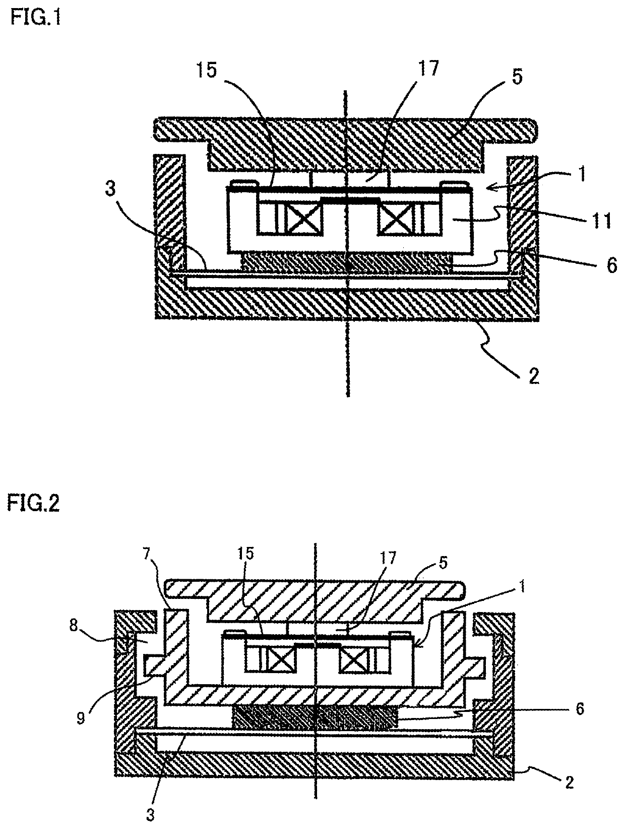
[0037]The bone conduction speaker main body 1 is provided with a contact 5 that is butted against an ear or a peripheral portion thereof when in use. Needless to say, the contact 5 is disposed such that it is located slightly above the casing 2. The bone conduction speaker main body 1 in a first embodiment, which is illustrated in FIG. 1, is disposed on the flat plate spring 3 through a weight 6 attached to the back face of the yoke 11 thereof. The heavier the weight 6, the larger the vibration suppressing effect thereof will be, however, the weight 6 is generally specified to be as heavy as approx. two times the weight of the bone conduction speaker main body 1. The contact 5 for transmitting a vibration to a human body is disposed on the diaphragm 15 of the bone conduction speaker main body 1 through the plate yoke 17.

[0038]In the first embodiment, the purpose for disposing the weight 6 on the bone conduction speaker main body 1 is to improve the frequency characteristics. In othe...

second embodiment

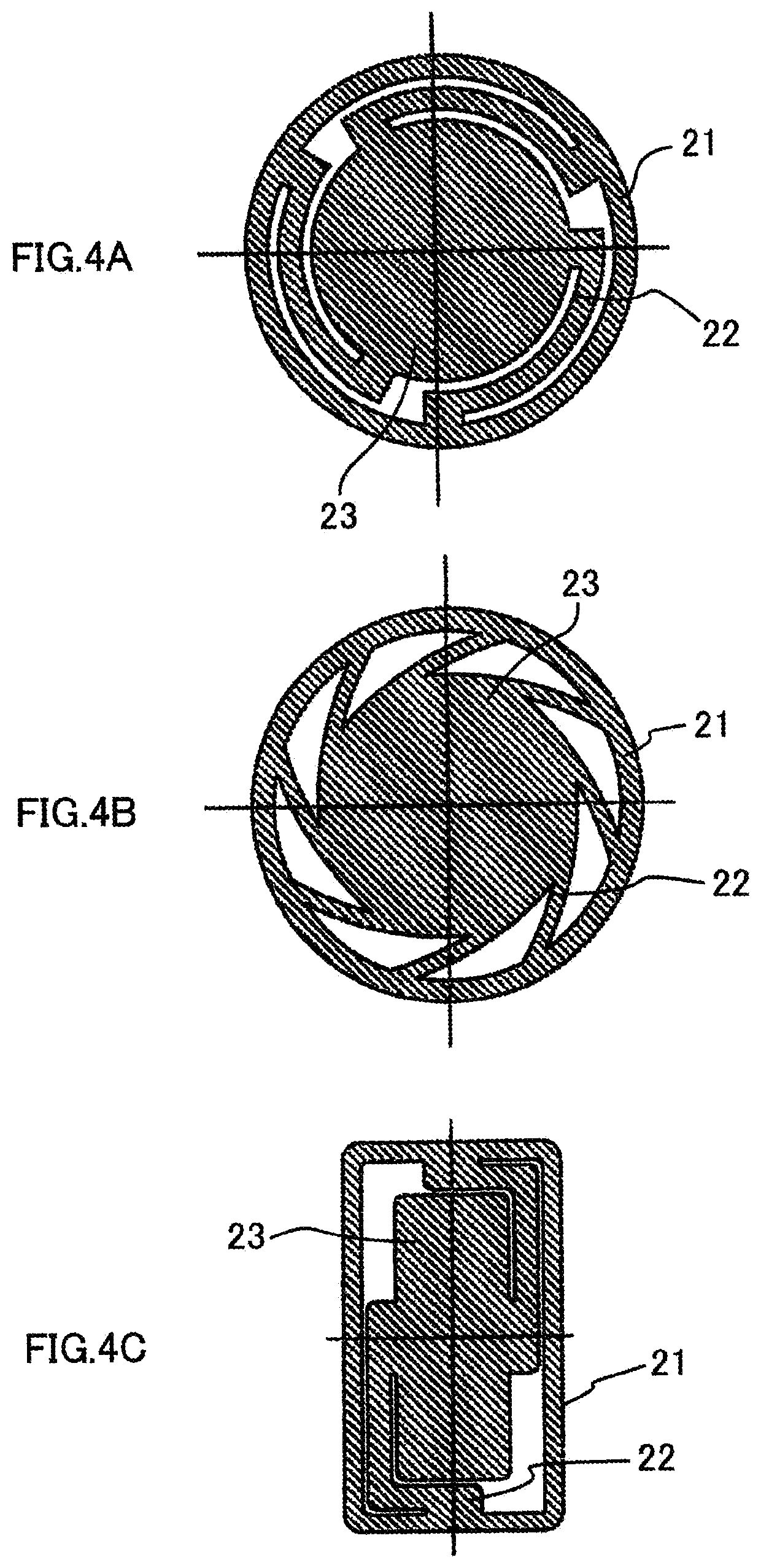
[0049]In a second embodiment, which is illustrated in FIG. 2, the bone conduction speaker main body 1 is accommodated in an inner casing 7, the contact 5 being separated from the top face thereof, and in such state, being incorporated in the casing 2. And to the back face of the inner casing 7, the weight 6 is attached, and the weight 6 is fixed onto the spring plate 23 of the flat plate spring 3. A peripheral groove 8 is formed in the inner side face of the casing 2, and in the outer side face of the inner casing 7, an outer peripheral flange 9, which is vertically moved in a non-contact manner at the time of the bone conduction speaker main body 1 being driven.

third embodiment

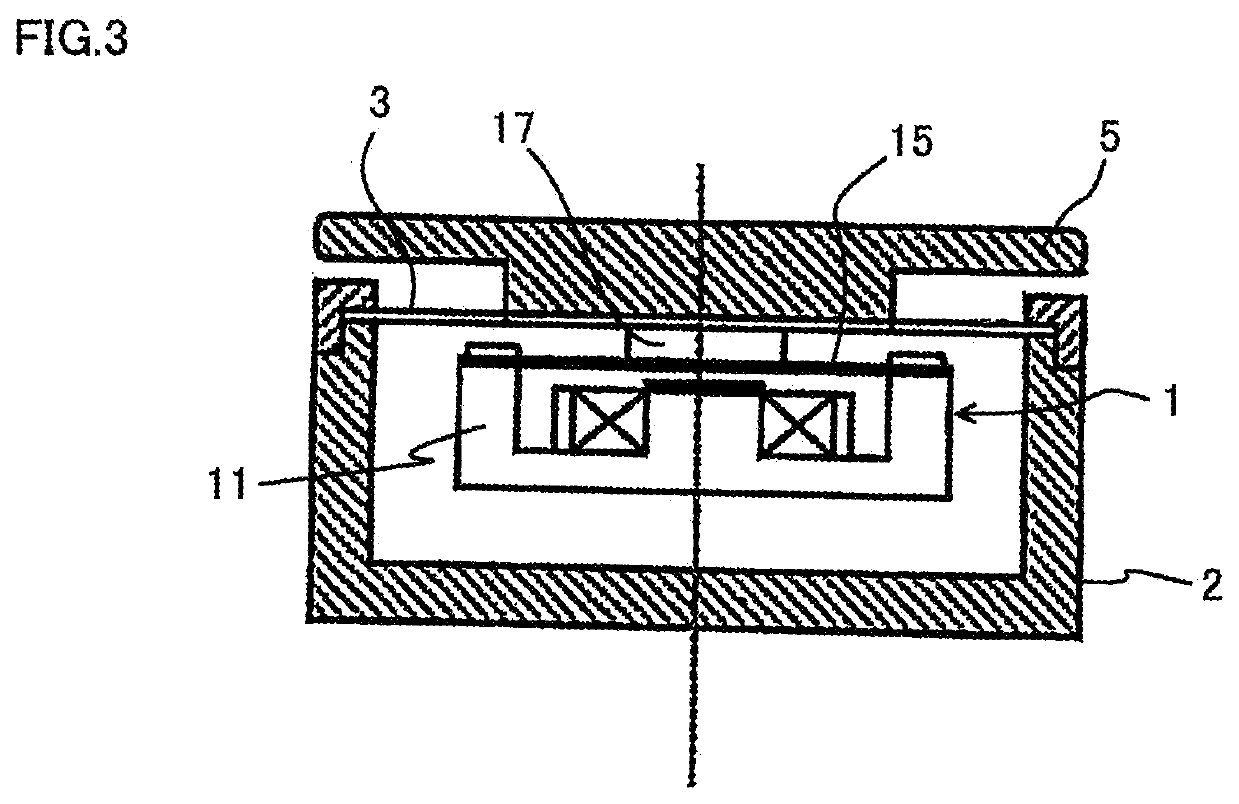
[0050]In a third embodiment, which is illustrated in FIG. 3, the bone conduction speaker main body 1 is suspended with the diaphragm 15 being fixed to the back face of the flat plate spring 3 through the plate yoke 17.

[0051]With the bone conduction speaker unit in accordance with the embodiments 1 and 2 of the present invention, at the time of non-calling, when a pressing force is not applied to the contact 5, the synergism of the weight 3 and the flat plate spring 3 provides a vibration suppressing effect, whereby generation of an unintended occurrence of sound leakage can be avoided.

[0052]The maximum feature of the bone conduction speaker unit in accordance with embodiments of the present invention resides in that it is provided with a structure with which a sound output generated in the bone conduction speaker main body 1 is always transmitted to the casing 2 through the flat plate spring 3, which holds the bone conduction speaker main body 1. Some of the bone conduction speakers...


PUM


Abstract

Provided is a bone conduction speaker unit with which, in order to improve the vibration characteristics, a vibration-suppressing structure is incorporated in a unit main body, whereby sound leakage and vibration from the unit as a single body can be suppressed. The bone conduction speaker unit, including a bone conduction speaker main body incorporated in a casing, uses a flat plate spring for holding the bone conduction speaker main body in the casing, the flat plate spring being disposed such that the direction of vibration of the bone conduction speaker main body being in parallel with the direction of vibration of the flat plate spring.

Description

CROSS-REFERENCE TO RELATED APPLICATIONS[0001]This application claims priority to PCT Application No. PCT / JP2018 / 046383, having a filing date of Dec. 17, 2018, based off of Japanese Application No. 2017-254539, having a filing date of Dec. 28, 2017, the entire contents of which are hereby incorporated by reference.FIELD OF TECHNOLOGY[0002]The following relates to a bone conduction speaker unit, and more particularly, to a bone conduction speaker unit that, upon being incorporated in a mobile phone, or the like, will not present a problem of sound leakage.BACKGROUND[0003]The bone conduction speaker unit converts a voice signal into a vibration to transmit it to the skull, and the like, being compact and lightweight and capable of being used even under noise, whereby, in recent years, it has been widely used with communication apparatuses, such as a mobile phone, and the like.[0004]In case where this bone conduction speaker unit is incorporated in a handset of telephone, there is a pos...

Claims


Application Information

Patent Timeline
Patent Type & Authority Applications(United States)
IPC IPC(8): H04R1/02
CPCH04R1/02H04R2499/11H04R9/043H04R9/066H04R2460/13
Inventor FUKUDA, MIKIO
Owner TEMCO JAPAN
Why Eureka
Try Eureka