Built-in antenna module of wireless communication terminal

a wireless communication terminal and built-in technology, applied in the structural form of radiating elements, resonant antennas, substantially flat resonant elements, etc., can solve the problems of difficult maintenance or increase the installation area of antennas, inconvenient carrying around, and possible damage, so as to maximize the utilization of limited space and improve the antenna's capabilities.

Inactive Publication Date: 2006-11-16
SAMSUNG ELECTRO MECHANICS CO LTD
View PDF1 Cites 5 Cited by
  • Summary
  • Abstract
  • Description
  • Claims
  • Application Information

AI Technical Summary

Benefits of technology

[0014] The present invention has been made to solve the foregoing problems of the prior art and it is therefore an object of the present invention to provide a built-in antenna module which efficiently utilizes a limited space in a terminal body with improved capabilities of an antenna.
[0019] Preferably, the radiator has the same dimensions as the upper surface of the base in order to maximize transmission and reception capability of the antenna.
[0027] More preferably, the built-in antenna module further includes a gasket between the upper base and the lower base for preventing sounds generated by the operator from leaking out of the base.
[0028] More preferably, the upper base and the lower base are bonded integrally with an adhesive to prevent sounds generated by the operator from leaking out of the base.
[0029] More preferably, the upper base and the lower base are bonded integrally via ultrasonic welding to prevent sounds generated by the operator from leaking out of the base.

Problems solved by technology

But as they are extended to the outside, they are much likely to be damaged by external force, inconvenient for carrying around, and may be a hindrance to attractive exterior design of the terminal.
However, with the limited space in the miniaturized terminal body, it is difficult to maintain or increase the installation area of the antenna.
Thus, in case of disposing the antenna module 2 coplanar with the actuator 10, there is a limitation in increasing the space for the antenna module to enhance the capabilities of the antenna.

Method used


Image

  • Built-in antenna module of wireless communication terminal
  • Built-in antenna module of wireless communication terminal
  • Built-in antenna module of wireless communication terminal

Examples


Embodiment Construction

[0050] Preferred embodiments of the present invention will now be described in detail with reference to the accompanying drawings.

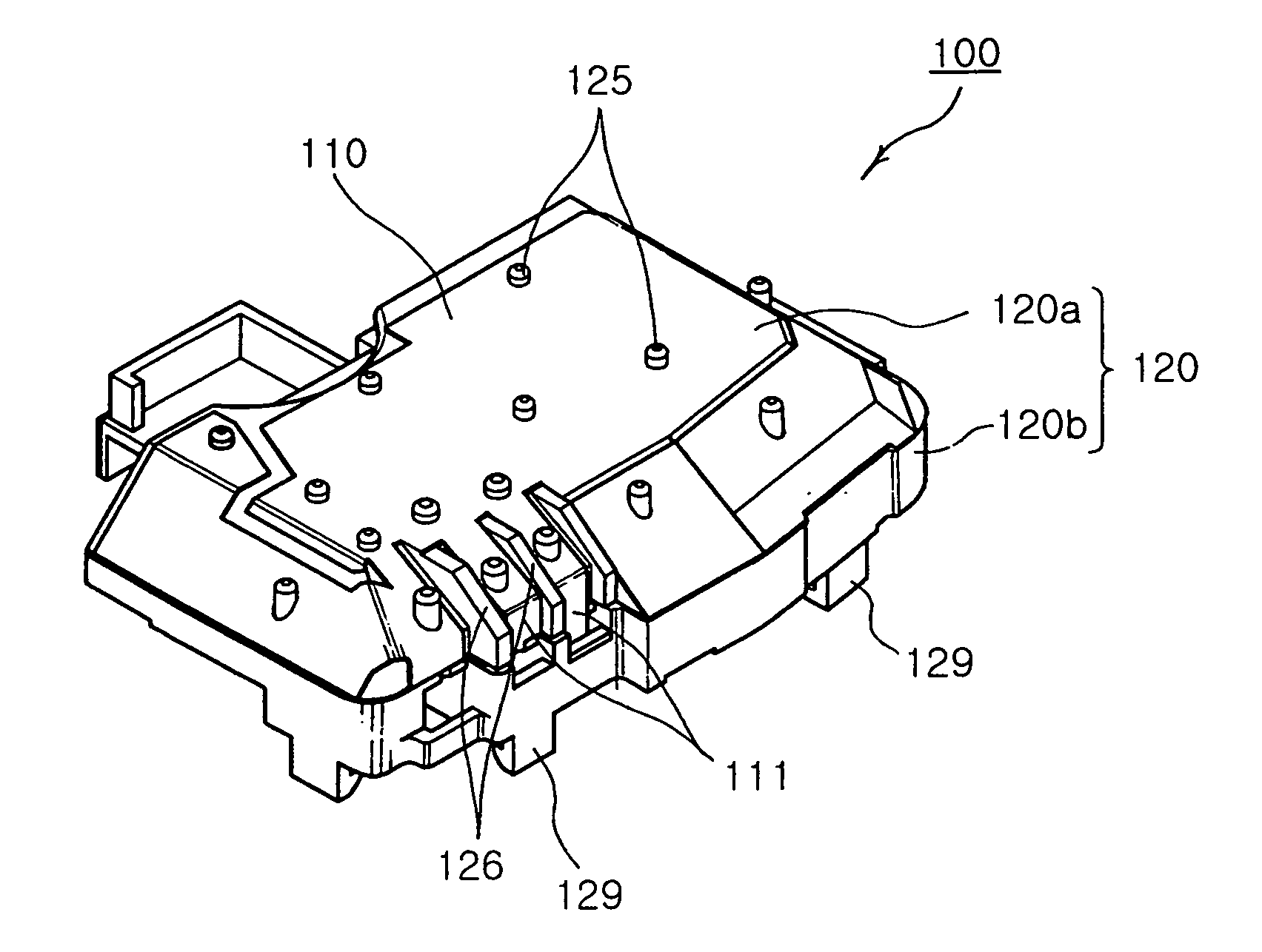
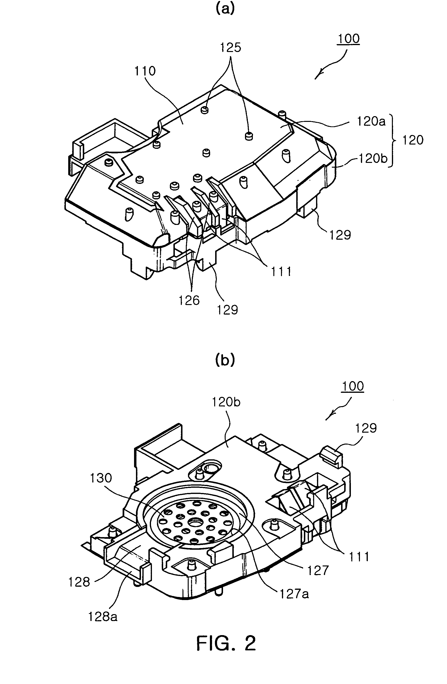
[0051] As shown in FIGS. 2 to 6, in an antenna module 100 of the present invention, an antenna component for transmitting and receiving an electrical wave is integrated with a component for generating sounds or vibrations indicating an incoming call, thereby efficiently utilizing an inner space of the wireless communication terminal. The antenna module 100 includes a radiator 110, a base 120 and an operator 130.

[0052] The radiator 110 is composed of at least one conductor disposed on an outer surface of the base 120. During a telephonic communication, the radiator 110 receives an electric signal from a board M provided in the terminal body, transforming the signal into an electrical wave to be radiated to the outside while receiving an electrical wave in a particular frequency band transmitted from the outside.

[0053] In addition, as shown in FIG. 2(a),...


PUM


Abstract

The invention relates to a built-in antenna module for a wireless communication terminal. The module includes at least one radiator. The module also includes a base having an inner space, disposed on a board of a terminal body, and having the radiator on an outer surface thereof to enable electric connection between an end of the radiator and the board of the terminal body. The module further includes an operator disposed in the inner space of the base for indicating an incoming call when power is supplied. The invention efficiently utilizes a limited space in the terminal body with enhanced capabilities of the antenna.

Description

CLAIM OF PRIORITY [0001] This application claims the benefit of Korean Patent Application No. 2005-39044 filed on May 10, 2005, in the Korean Intellectual Property Office, the disclosure of which is incorporated herein by reference. BACKGROUND OF THE INVENTION [0002] 1. Field of the Invention [0003] The present invention relates to an antenna installed inside a wireless communication terminal, and more particularly, a built-in antenna module for a wireless communication terminal, in which an operator for generating sounds or vibrations indicating an incoming call is housed in a component, thereby efficiently utilizing a limited space in a miniaturized wireless communication terminal. [0004] 2. Description of the Related Art [0005] In general, a wireless communication terminal refers to a portable communication device capable of transmitting and receiving voices and texts and image data through wireless communication. The examples include a personal communication service (PCS) termin...

Claims


Application Information

Patent Timeline
Patent Type & Authority Applications(United States)
IPC IPC(8): H01Q1/24
CPCH01Q1/243H01Q9/0421H01Q9/0407H01Q1/38H01Q1/44H01Q1/20H04B1/3833
Inventor HAN, SUN KYULEE, WOOK HEE
Owner SAMSUNG ELECTRO MECHANICS CO LTD
Why Eureka
Try Eureka