
Space frame center upper frame connection

a technology for space frames and upper frames, applied in the field of space frames, can solve the problems of consuming less fuel, requiring many meters of welding to fabricate a completed frame, and a particular difficulty in hauling trucks,

Active Publication Date: 2021-04-29
CATERPILLAR INC
View PDF0 Cites 29 Cited by
  • Summary
  • Abstract
  • Description
  • Claims
  • Application Information

AI Technical Summary

Benefits of technology

The patent text describes a center upper frame connection casting for a space frame used on off-highway rear haul trucks. The casting includes a solid center boss, a rearward mounting surface, a rearward angular center upper frame tube connection boss, a vertical center upper frame tube connection boss, a forward angular center upper frame tube connection boss, and a forward angular mounting surface. The technical effect of this invention is to provide a reliable and stable connection between the center upper frame and other frame tubes in the space frame, ensuring the vehicle's strength and stability during operation.

Problems solved by technology

Conventional haul trucks, such as off-highway rear haul trucks, may use welded steel frames that can be extremely heavy and may require many meters of welding to fabricate a completed frame.
For example, haul trucks with space frames comparatively can haul larger payloads and consume less fuel.
However, vehicular applications are, at least in part, dynamic in nature, and haul trucks can represent a particularly difficult application because of loads applied to the space frame as well as bending, twisting, and / or flexing that can occur as the haul truck travels on various types of terrain, such as off highway terrain.

Method used


Image

  • Space frame center upper frame connection
  • Space frame center upper frame connection
  • Space frame center upper frame connection

Examples


Embodiment Construction

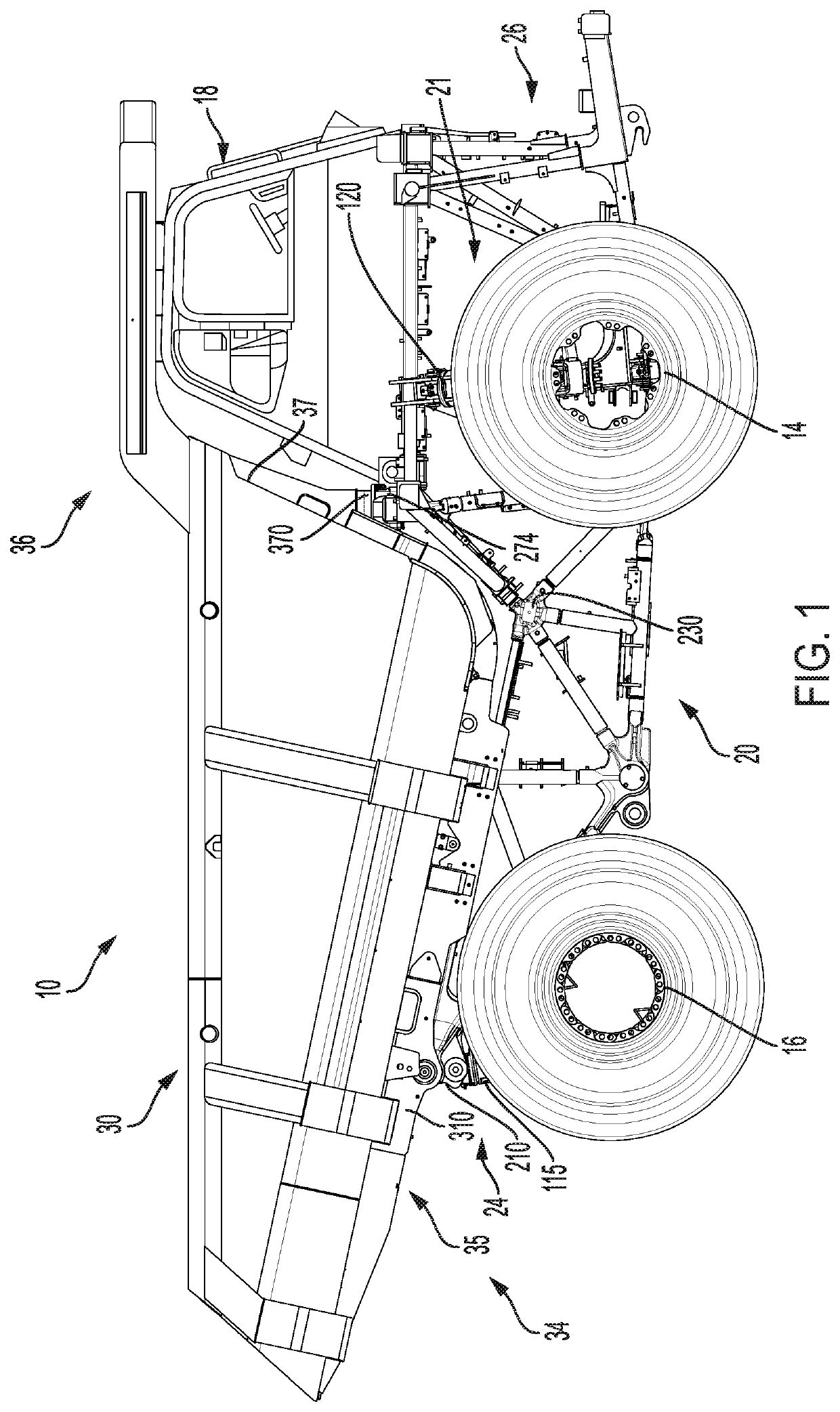
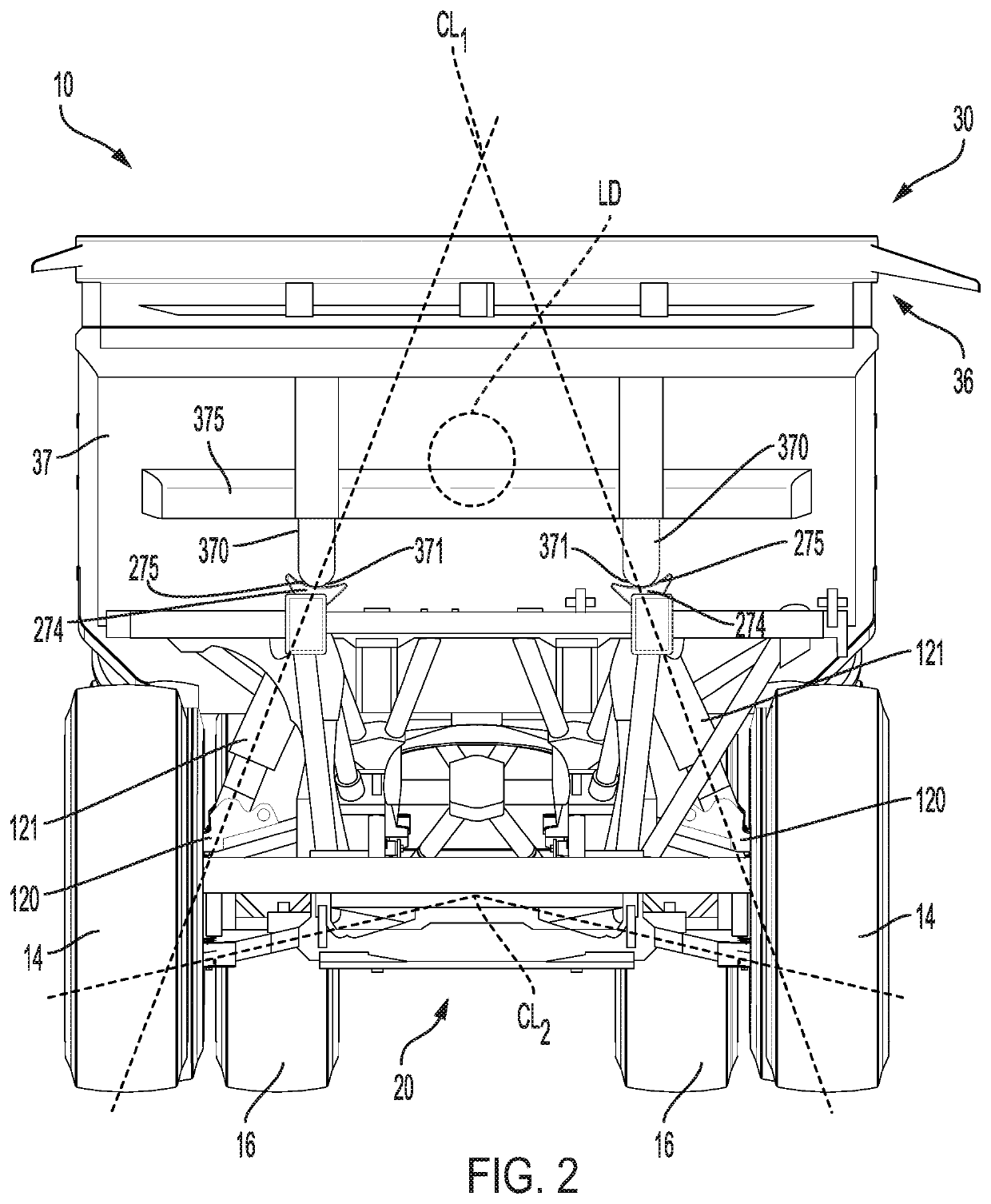
[0015]Referring now to the drawings and with specific reference to FIG. 1 and FIG. 2, these figures illustrate an exemplary embodiment of a machine 10. Machine 10 may be a mobile machine that performs some type of operation associated with an industry such as mining, construction, or any other industry known in the art. For example, as shown in FIG. 1 and FIG. 2, machine 10 may be an earth moving machine, particularly, an off-highway rear haul truck 10.

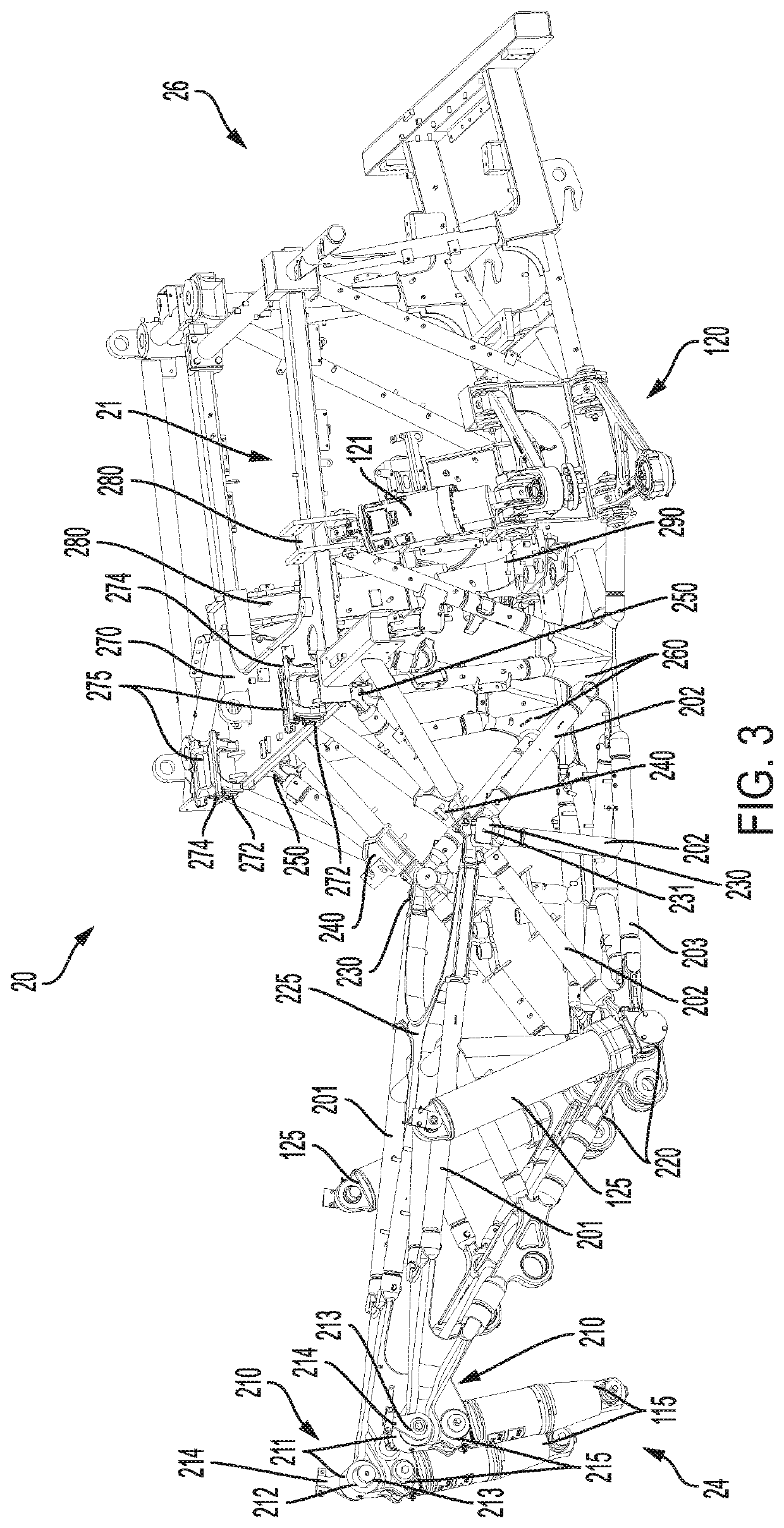
[0016]Machine 10 may have a space frame 20 supported by front wheels 14 and rear wheels 16 (including respective tires). The front and rear wheels 14, 16 may be connected to space frame 20 by front suspension members and rear suspension systems, respectively. Machine 10 may also include a bed or body 30 supported by the space frame 20. Such bed or body 30 may be referred to herein as a dump body 30. The dump body 30 can be configured as a receptacle to receive hauling material.

[0017]A rear portion 34 of the dump body 30 can be pivotab...


PUM


Abstract

A center upper frame connection for a space frame can comprise a center boss; a rearward mounting surface facing rearward; a rearward angular center upper frame tube connection boss oriented downward and rearward; a vertical center upper frame tube connection boss oriented downward; a forward angular center upper frame tube connection boss oriented forward and downward; and a forward angular mounting surface facing forward and upward. The rearward mounting surface can fixedly attach a center upper horizontal frame connection, the rearward angular center upper frame tube connection boss can fixedly attach a first elongate support structure, the vertical center upper frame tube connection boss can fixedly attach a second elongate support structure, the forward angular center upper frame tube connection boss can fixedly attach to a third elongate support structure, and the forward angular mounting surface can fixedly attach a center upper frame nodal connection.

Description

TECHNICAL FIELD[0001]The present disclosure relates to space frames, and more particularly to space frame center upper frame connections, and systems, components, and methods thereof.BACKGROUND[0002]Conventional haul trucks, such as off-highway rear haul trucks, may use welded steel frames that can be extremely heavy and may require many meters of welding to fabricate a completed frame. Space frames offer a lighter and stronger alternative to traditional welded steel frames, since far less steel is required. As a result, space frames offer considerable benefits in terms of cost, manufacturability, and performance. For example, haul trucks with space frames comparatively can haul larger payloads and consume less fuel.[0003]Conventional space frame structures may use fabricated nodal connections. Such nodal connections may be used to create space frame structures associated with static applications. However, vehicular applications are, at least in part, dynamic in nature, and haul tru...

Claims


Application Information

Patent Timeline
Patent Type & Authority Applications(United States)
IPC IPC(8): B62D21/08B62D21/09B62D27/02B62D65/02
CPCB62D21/08B62D65/02B62D27/023B62D21/09B62D33/00B62D21/186B60P1/28
Inventor MILLER, TAD W.
Owner CATERPILLAR INC
Learn More