Rotor tooth crack inspection method
- Summary
- Abstract
- Description
- Claims
- Application Information
AI Technical Summary
Benefits of technology
Problems solved by technology
Method used
Image
Examples
embodiment 1
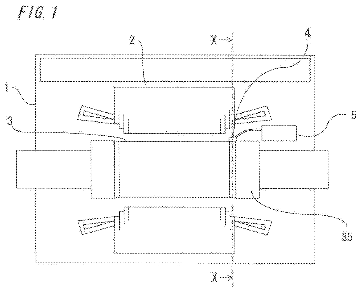
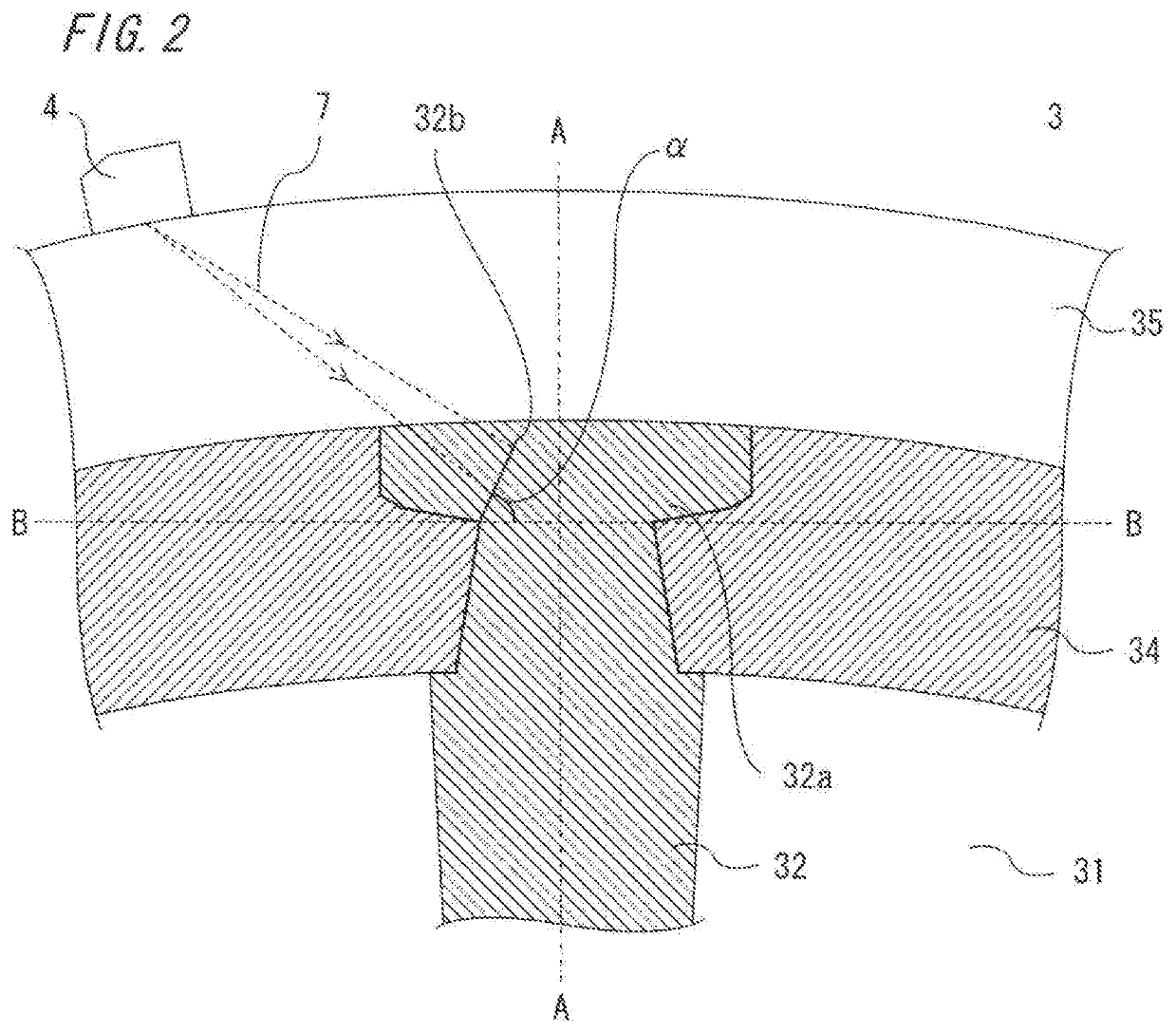
[0020]FIG. 1 is a plan view showing a schematic structure of a turbine electric generator to which a rotor tooth crack inspection method according to embodiment 1 of the present disclosure is applied, and FIG. 2 is a partial sectional view along line X-X in FIG. 1.
[0021]In the turbine electric generator, a rotor 3 is rotatably provided inside a stator 2 supported by a frame 1. In the rotor 3, a plurality of slots 31 are radially formed in the radial direction so as to be arranged along the circumferential direction of an armature core, teeth 32 are formed between the slots 31, and field coils for generating a magnetic field (not shown) are wound around the teeth 32 and stored in the slots 31.
[0022]The field coils are layered and arranged in the slots 31, and in order that each field coil does not come out of the slot 31 by a centrifugal force due to rotation of the rotor 3, a wedge 34 having a wedge shape is inserted into a groove formed at a tooth shoulder portion 32a, and further,...
PUM
 Abstract
Description
Claims
Application Information
 - R&D
- Intellectual Property
- Life Sciences
- Materials
- Tech Scout
- Unparalleled Data Quality
- Higher Quality Content
- 60% Fewer Hallucinations
Browse by: Latest US Patents, China's latest patents, Technical Efficacy Thesaurus, Application Domain, Technology Topic, Popular Technical Reports.
© 2025 PatSnap. All rights reserved.Legal|Privacy policy|Modern Slavery Act Transparency Statement|Sitemap|About US| Contact US: help@patsnap.com


