
A pipetting apparatus, a liquid handling system and a method of controlling pipetting

a liquid handling system and pipetting technology, applied in the field of pipetting apparatuses, can solve the problems of cumbersome inputting of respective liquid classes, time-consuming, and inability of pipetting apparatuses

Active Publication Date: 2021-03-18
TECAN TRADING AG
View PDF0 Cites 0 Cited by
  • Summary
  • Abstract
  • Description
  • Claims
  • Application Information

AI Technical Summary

Benefits of technology

The present invention is a pipetting apparatus that can measure the sample fluid through a pipette tube and control the pressure generating means based on the measurement value. This allows for real-time control of the aspiration parameters, adapting to the behavior of the sample fluid. The apparatus can also determine the volume level of the sample fluid and provide reliable process security, as well as automated liquid class optimization. The technical effects of this invention include improved precision and efficiency in sample fluid manipulation and optimization of workflow setup.

Problems solved by technology

It is a problem in the state of the art that pipetting apparatuses are unable of pipetting fluids which are undefined (e.g. undefined liquid classes).
Inputting respective liquid classes is cumbersome, time consuming and can be a source of errors.

Method used


Image

  • A pipetting apparatus, a liquid handling system and a method of controlling pipetting
  • A pipetting apparatus, a liquid handling system and a method of controlling pipetting

Examples


Embodiment Construction

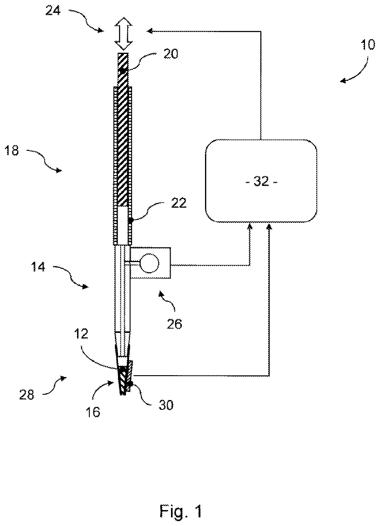
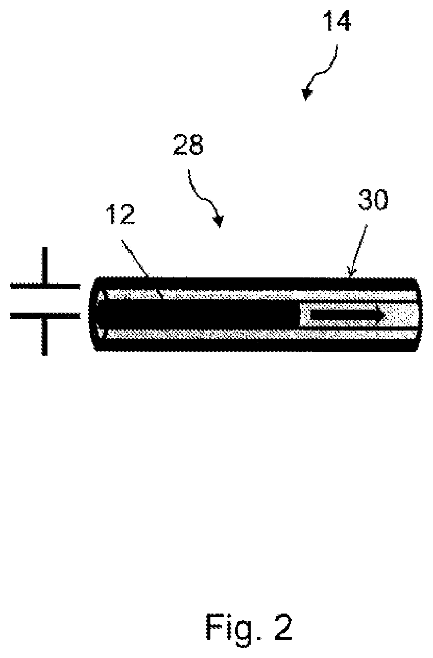
[0037]FIG. 1 schematically depicts a pipetting apparatus 10 for aspirating and / or dispensing of sample fluid 12 inside a pipette tube 14. The sample fluid 12 is aspirated into or dispensed out of the pipette tube 14 via a disposable tip 16. While not shown, the pipette tube 14 can be formed integrally, i.e. without the disposable tip. The opposing end of the pipette tube 14 is operationally connected to a pressure generating means 18, such as a plunger / cylinder arrangement, a pump, etc. In the shown example, the pressure generating means 18 comprises a combination of a plunger 20 which is inserted into a cylinder 22. Said plunger 20 is axially movable within said cylinder 22 in a circumferentially sealed manner, adapted to vary the pressure inside the cylinder 22. Further comprised is a movement means 24 (schematically depicted as a double-arrow) configured to move the plunger 20 in relation to the cylinder 22.

[0038]The pipetting apparatus 10 further comprises a pressure measurement...


PUM


Abstract

A pipetting apparatus having a pipette tube with a first end provided with an opening for aspirating and / or dispensing of a sample fluid and a second end operationally connected to a pressure generating means. The pipetting apparatus has at least one measuring unit adapted to determine at least one measurement value of the sample fluid based on the aspirating and / or dispensing of the sample fluid and to provide a sample fluid measurement signal representative thereof to an output of the measuring unit. The pipetting apparatus also has a control circuit operationally coupled to the output of the measuring unit and the input of the pressure generating means, the control circuit is configured to control said pressure generating device based on the sample fluid measurement signal.

Description

TECHNICAL FIELD[0001]The present invention is related to a pipetting apparatus for aspirating and / or dispensing volumes of fluids. Such a pipetting apparatus can be part of an automated fluid handling system as commonly used in medical, pharmaceutical and chemical laboratories, where sample fluids need to be processed quickly and reliably. The present invention is further related to a liquid handling system and a method of controlling pipetting in a pipetting apparatus.BACKGROUND OF THE INVENTION[0002]Laboratories conducting large-scale sample analysis in the medical, pharmaceutical or chemical industries require systems for rapidly and reliably handling fluid volumes. Pipetting of the sample fluids is at the core of these processes. Therefore, automated laboratory systems usually comprise one or more pipetting apparatuses operating on liquid containers situated e.g. on a worktable. One or more robots (in particular robotic arms) may be used for operating on such a worktable surface...

Claims


Application Information

Patent Timeline
IPC IPC(8): B01L3/02G01N11/04G01N13/02G01N35/10
CPCB01L3/0217G01N11/04G01N13/02B01L2400/0478G01N2035/1025B01L2300/0832G01N35/1016
Inventor OTT, PHILIPP
Owner TECAN TRADING AG
Learn More