
Intensity-Normalized Image Sensor

a technology of intensity-normalized image and sensor, which is applied in the field of intensity-normalized image sensor, can solve the problems of large dynamic range that the sensor is called upon to handle, deleterious secondary effects, and inability to provide the necessary dynamic range for capturing images in low light conditions

Active Publication Date: 2021-03-11
ROBERT BOSCH GMBH
View PDF0 Cites 3 Cited by
  • Summary
  • Abstract
  • Description
  • Claims
  • Application Information

AI Technical Summary

Benefits of technology

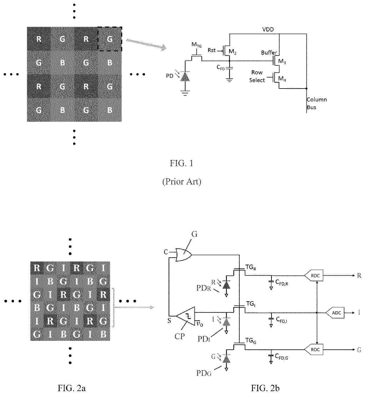
The patent describes an image sensor that has multiple rows and columns of pixels. Each pixel has a corresponding filter, including RGB filters in a specific pattern. Additionally, some pixels have an all-pass optical filter that enables the sensor to measure the intensity of the optical signal. The filters are arranged in a specific pattern, where the patterns are alternated between columns. Each pixel also includes a photodiode, transfer gate, and floating diffusion, with the transfer gate being controlled by either a separate synchronous control signal or an asynchronous signal generated by the all-pass filter. The sensor can digitize the charge on the floating diffusion of the different pixels based on the intensity of the optical signal, providing information about the optical signal detected by the sensor. The technical effect of this arrangement is improved image quality and reduced noise in the image sensor.

Problems solved by technology

One of the challenges in the design of image sensors is the large dynamic range that the sensors are called upon to handle.
The problem becomes accentuated when this large dynamic range must be supported by millions of pixels operating in parallel.
However, capturing pixels with different brightness at different time intervals can cause deleterious secondary effects, such as motion bluffing when imaging a dynamic scene.
While this architecture works under normal lighting condition, it is not capable of providing the necessary dynamic range for capturing images in low light conditions, such as at night-time, or in bright daylight.
While this is an important improvement, it does come with some problems and limitations.
Hence, in the case of moving objects, this can cause bluffing in the image because different pixels might be captured at different time instants based on the intensity of light in their positions.
Secondly, the light intensity can vary by 8 orders of magnitude or 160 dB, which is not easily achievable even when relaxed by a few tens of dB using the multi-integration-time technique.
Theoretically, integration windows with larger difference, or even more integration windows, could be used to further relax the dynamic range, but this all would come at the cost of extra bluffing and other artifacts that could degrade the image quality.

Method used


Image

  • Intensity-Normalized Image Sensor

Examples


Embodiment Construction

[0012]For the purposes of promoting an understanding of the principles of the disclosure, reference will now be made to the embodiments illustrated in the drawings and described in the following written specification. It is understood that no limitation to the scope of the disclosure is thereby intended. It is further understood that the present disclosure includes any alterations and modifications to the illustrated embodiments and includes further applications of the principles disclosed herein as would normally occur to one skilled in the art to which this disclosure pertains.

[0013]The present disclosure provides a different approach to address the problems of the prior art image sensors discussed above. In most cases when there is a bright pixel, it is not necessarily useful to know the precise brightness of the pixel. Instead, it is useful to identify it as a bright pixel and to measure the RGB content of the light reaching that pixel. In particular, the sensors and methods des...


PUM


Abstract

An image sensor has a plurality of rows and columns of pixels, including RGB and bandpass I filters in a predetermined pattern shifted between adjacent columns so that none of the RGBI filters is adjacent the same type of filter. Each pixel includes a photodiode, a transfer gate and a floating diffusion. The transfer gate for all pixels in a pattern is controlled by the same signal, which can be a separate synchronous control signal controlled based on a predefined integration period or an asynchronous signal generated internally by the bandpass filter I and that is compared to a predefined voltage level indicative of a predetermined intensity at filter I. Upon activation of either signal, the integration period for the pixels ends and the charge on the floating diffusion for the R, G and B pixels is digitized in relation to the bandpass pixel I using a ratio-to-digital converter.

Description

PRIORITY CLAIM[0001]This application is a utility filing from and claims priority to co-pending U.S. Provisional Application No. 62 / 608,759, filed on Dec. 21, 2017, the entire disclosure of which is incorporated herein by reference.BACKGROUND[0002]One of the challenges in the design of image sensors is the large dynamic range that the sensors are called upon to handle. For example, the intensity of light in a dark environment versus the intensity under bright sunlight varies by eight orders of magnitude. This variation translates to 160 dB dynamic range in the amount of charge collected in a photodiode-based pixel with a constant integration time. The problem becomes accentuated when this large dynamic range must be supported by millions of pixels operating in parallel. Sophisticated electronic circuits capable of handling this dynamic range necessarily have a large on-chip footprint per pixel, which eliminates such circuits as a viable option in the design of image sensors.[0003]On...

Claims


Application Information

Patent Timeline
IPC IPC(8): H04N5/353H01L27/146H04N9/04H04N5/378H04N5/355
CPCH04N5/3537H01L27/14645H04N5/35554H04N9/04559H04N5/378H01L27/14605H01L27/14621H01L27/14685H01L27/146H04N25/534H04N25/135H04N25/78H04N25/75H04N25/583
Inventor WOJCIECHOWSKI, KENLAJEVARDI, PEDRAMBEHROOZPOUR, BEHNAMBACK, KRISTINE JULIANE
Owner ROBERT BOSCH GMBH
Learn More