
System and Apparatus For Determining the Position of Railbound Vehicles on a Railway System

a technology of railbound vehicles and positioning devices, which is applied in the direction of railway traffic control systems, railway components, railway signalling and safety, etc., can solve the problems of high maintenance costs, high investment requirements, and low positioning resolution of such systems

Pending Publication Date: 2021-03-11
ECOMELA
View PDF0 Cites 9 Cited by
  • Summary
  • Abstract
  • Description
  • Claims
  • Application Information

AI Technical Summary

Benefits of technology

The patent is about a new control system for rail-bound vehicles, like a train, that solves problems with existing systems. The technical effects of this invention are to make it easier to control the movement of these vehicles and make them safer.

Problems solved by technology

All three have in common that special devices must be installed at close intervals throughout the rail network, devices which serve no purpose apart from train positioning, and thus require an expensive investment and bear high maintenance costs.
In addition, the positioning resolution of such systems is very low, and directly tied to the number of detection devices installed along the track.
Thus, increasing positioning resolution is very costly.
However, the reliability and availability of satellite-based positioning is not considered good enough for critical systems: the radio signals from the satellites are very weak, and thus are easily jammed or disturbed by intentional or non-intentional interference.
Further, such signals do not penetrate into tunnels, making satellite-based positioning unavailable in tunnels and subway networks, for example.

Method used


Image

  • System and Apparatus For Determining the Position of Railbound Vehicles on a Railway System
  • System and Apparatus For Determining the Position of Railbound Vehicles on a Railway System
  • System and Apparatus For Determining the Position of Railbound Vehicles on a Railway System

Examples


Embodiment Construction

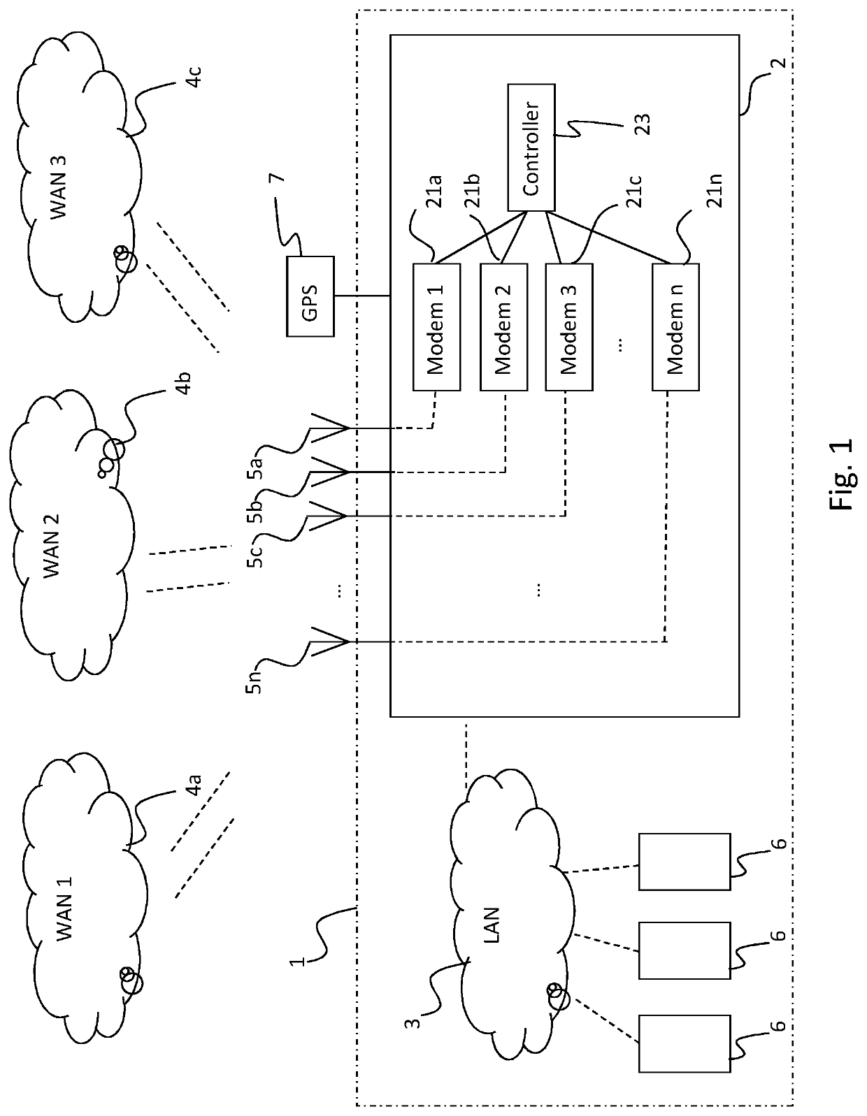
[0055]In the following detailed description, preferred embodiments of the invention will be described. However, it is to be understood that features of the different embodiments are exchangeable between the embodiments and may be combined in different ways, unless anything else is specifically indicated. Even though in the following description, numerous specific details are set forth to provide a more thorough understanding of the invention, it will be apparent to one skilled in the art that the invention may be practiced without these specific details. In other instances, well known constructions or functions are not described in detail, so as not to obscure the invention. In the detailed embodiments described in the following are related to trains. However, it is to be acknowledged by the skilled reader that the method and system are correspondingly useable on other rail-bound vehicles. In particular, the invention is very well suited for use in underground railway systems.

[0056]...


PUM


Abstract

A method and system for determining a position of a rail-bound vehicle on a railway is disclosed. The apparatus comprises: a transmitter and receiver for wireless communication with at least one base station arranged at a predetermined position in the vicinity of the railway; a measurement device to determine a distance to said at least one base station based on measurements of the radio signals of said wireless communication in the time domain and / or phase domain; and a controller arranged to determine a present position of said vehicle on said railway based on said distance. A control system / method for controlling rail-bound vehicles in a railway system, and / or an internal or external system related to such rail-bound vehicles, using such position determination is also disclosed.

Description

CROSS-REFERENCE TO RELATED APPLICATIONS[0001]This application is the U.S. national phase of, and claims priority to, International Application No. PCT / SE2019 / 050474, filed May 23, 2019, which designated the U.S. and which claims priority to Swedish Patent Application No. 1850624-6, filed May 24, 2018.TECHNICAL FIELD OF THE INVENTION[0002]The invention relates to a method and system for determining the position of rail-bound vehicles, such as trains, on any type of railway system, and is of particular advantage for railway systems arranged underground, such as for metros, subways and the like, where alternate means such as GNSS are not available.BACKGROUND[0003]There has long existed a need for knowing and determining the position of rail-bound vehicles on a railway system. The need for technological means to determine and relay the location of rolling stock in a rail network is primarily used for two categories of purposes. Firstly, for remote awareness and overview: allowing a pers...

Claims


Application Information

Patent Timeline
IPC IPC(8): B61L27/00B61L25/02
CPCB61L27/0061B61L25/025B61L27/0005B61L15/0027B61L2205/02B61L2205/04B61L2027/204B61L25/021B61L27/70B61L27/30
Inventor BJURSTRÖM, JOEL
Owner ECOMELA
Learn More