
Method and apparatus for automatic interleaving of cycled loads in a microgrid

a micro-grid and automatic interleaving technology, applied in the field of smart loads in the micro-grid, can solve the problems of affecting the robustness of the system, adding cost, and complexity

Active Publication Date: 2021-02-25
ENPHASE ENERGY
View PDF0 Cites 1 Cited by
  • Summary
  • Abstract
  • Description
  • Claims
  • Application Information

AI Technical Summary

Benefits of technology

The present invention is about a system for automatically combining and timing loads in a microgrid. The technical effect of this system is better efficiency and reliability in combining these loads, which can help to reduce energy waste and improve overall performance of the microgrid.

Problems solved by technology

Although such coordination could be achieved in a relatively straightforward manner using communications, the additional required networking equipment and controllers would add cost, complexity, and hinder robustness of the system.

Method used


Image

  • Method and apparatus for automatic interleaving of cycled loads in a microgrid
  • Method and apparatus for automatic interleaving of cycled loads in a microgrid
  • Method and apparatus for automatic interleaving of cycled loads in a microgrid

Examples


Embodiment Construction

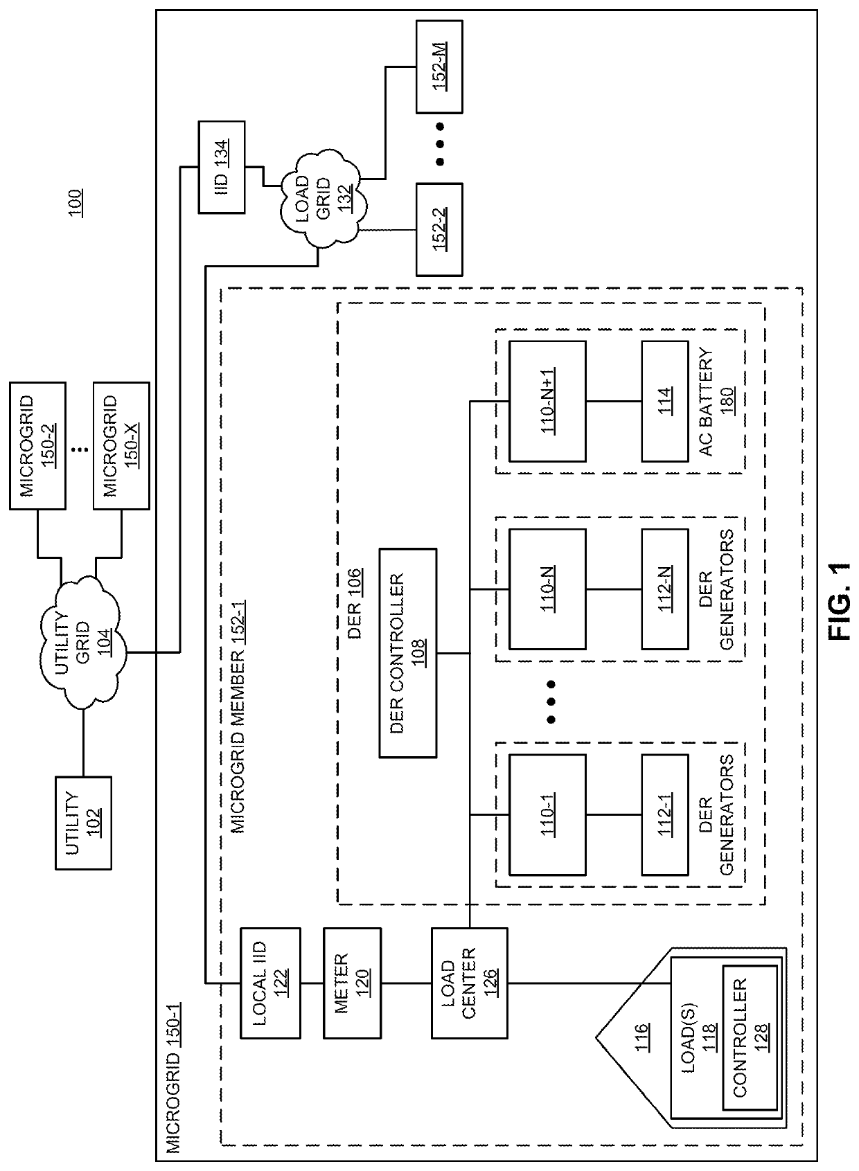
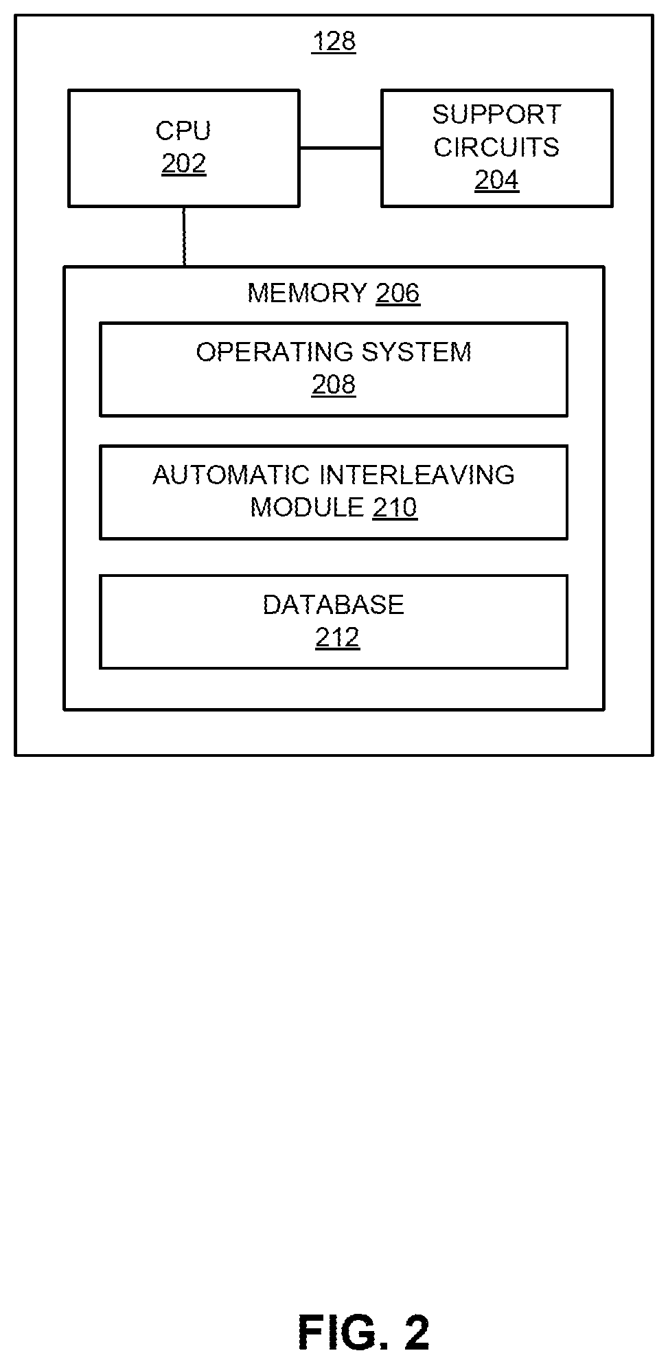
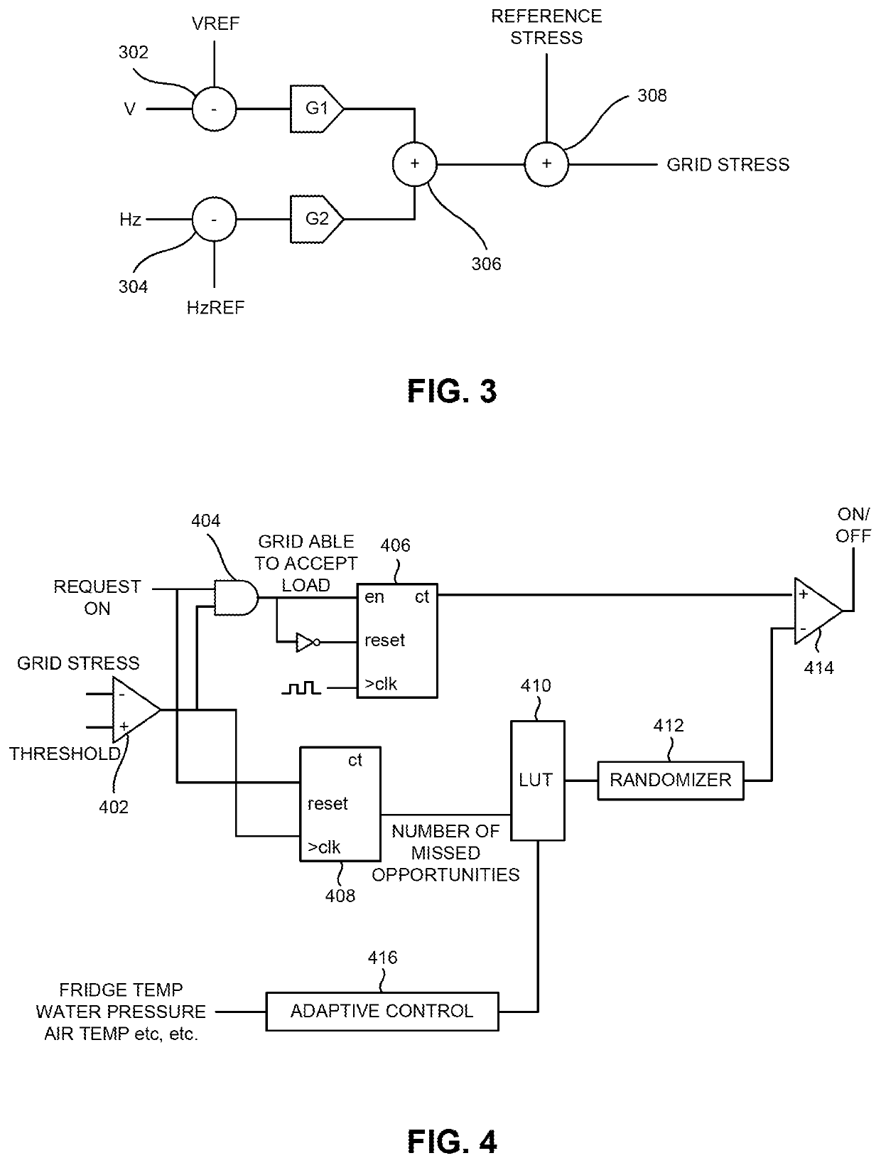
[0016]Embodiments of the present invention generally relate to a method and apparatus for autonomous, automatic interleaving of cycled loads in a microgrid. In one or more embodiments, a distributed, autonomous, communicationless technique is utilized by a plurality of cycled smart loads in a microgrid to decrease the likelihood of more than one of the cycles loads will activate at the same time and thereby increase the level of stress on the grid above a desired threshold.

[0017]The loads employing the techniques described herein, which may be referred to as “smart loads”, typically run at low duty cycles (e.g., refrigerators, well pumps, furnaces in well-insulated homes, and the like) and often pull very high power (e.g., electric dryers, washing machines, and the like). The techniques described herein allow a smart load to autonomously and opportunistically activate (i.e., turn on) and deactivate (i.e., turn off) using locally-measured information regarding the grid state (i.e., a...


PUM


Abstract

A method and apparatus for autonomous, automatic interleaving of cycled loads coupled to a grid. In one or more embodiments, the method comprises (i) determining, by a smart load coupled to a grid, a first grid stress value; (ii) comparing, by the smart load, the first grid stress value to an activation threshold; (iii) waiting, by the smart load, when the first grid stress value is less than the activation threshold, a delay period; (iv) determining, by the smart load and after the delay period ends, a second grid stress value; (v) comparing, by the smart load, the second grid stress value to the activation threshold; and (iv) activating, by the smart load, when the second grid stress value is less than the activation threshold.

Description

CROSS-REFERENCE TO RELATED APPLICATION[0001]This application claims benefit of U.S. provisional patent application Ser. No. 62 / 879,919, titled “Automatic Interleaving of Cycled Loads in a Microgrid” and filed Jul. 29, 2019, which is herein incorporated in its entirety by reference.BACKGROUND OF THE INVENTIONField of the Invention[0002]Embodiments of the present disclosure relate generally to smart loads in a microgrid and, more particularly, to autonomous, automatic interleaving of cycled smart loads in a microgrid.Description of the Related Art[0003]A conventional microgrid generally comprises at least one energy generator, at least one energy storage device, and at least one energy load. In small microgrids, a lack of load diversity can create a large peak-power-to-average-power ratio as a small collection of large but intermittent loads cycle on and off. Many of these loads are quite flexible as to when they can cycle on and off with little to no effect on the user. For example, ...

Claims


Application Information

Patent Timeline
Patent Type & Authority Applications(United States)
IPC IPC(8): H02J3/14H02J3/38G05B19/042
CPCH02J3/14G05B2219/2639G05B19/042H02J3/381H02J3/388H02J3/144H02J13/00016H02J13/00022Y02B70/3225Y04S20/222H02J2310/58H02J3/28H02J2310/10Y04S40/124Y04S40/126Y02E60/00Y04S20/12Y04S20/242Y02B70/30Y02B90/20H02J3/466H02J2310/14G01D2204/30G06Q50/06G01D2204/12Y04S20/30Y04S20/221Y04S10/50
Inventor ZIMMANCK, DONALD RICHARDFOMAGE, MARTIN
Owner ENPHASE ENERGY
Learn More