
Control method for image projection system and image projection system

Active Publication Date: 2021-02-04
SEIKO EPSON CORP
View PDF0 Cites 2 Cited by
  • Summary
  • Abstract
  • Description
  • Claims
  • Application Information

AI Technical Summary

Benefits of technology

This patent is about a control method for an image projection system using multiple projectors. The method involves determining the colors of pattern images that will be projected by the different projectors and making sure that the colors of the superimposed images are the same or different. The determined colors can be white or different from the superimposition number. The method also takes into account the relative luminous efficiency of the projectors and the sizes of the pattern images. Overall, this method helps ensure consistent and high-quality image projection.

Problems solved by technology

However, when the positions of the projected images projected from the respective plurality of projectors greatly deviate from one another, it is likely that the projected image correction device described in Patent Literature 1 cannot correct the positions of the projected images.
When a user manually adjusts the positions of the projected images, it is difficult for the user to visually recognize to which degree the projected images overlap one another when the white test images are projected at the different timings as in the projected image correction device described in Patent Literature 1.
Further, even when the respective plurality of projectors project the test images at the same timing, it is also difficult for the user to visually recognize how the projected image from which projector deviates.

Method used


Image

  • Control method for image projection system and image projection system
  • Control method for image projection system and image projection system
  • Control method for image projection system and image projection system

Examples


Embodiment Construction

[0027]An embodiment is explained below with reference to the drawings.

1. Configuration of an Image Projection System

1-1. Overall Configuration of the Image Projection System

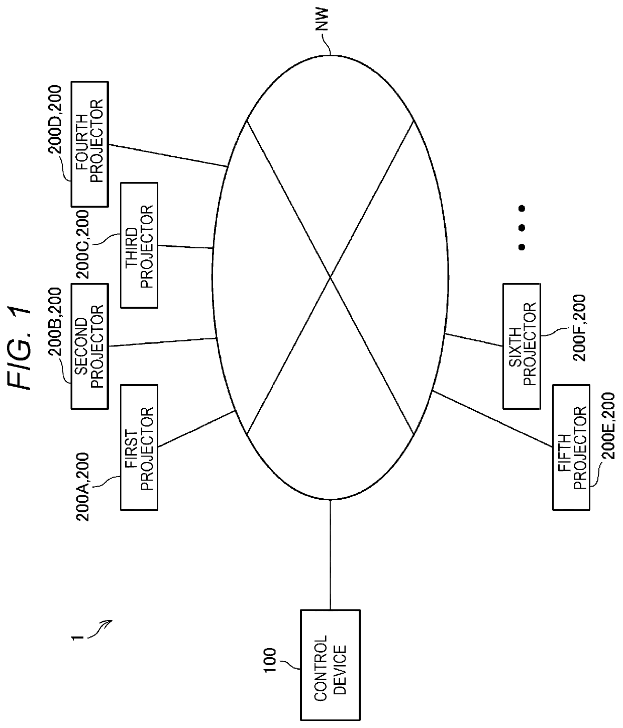
[0028]FIG. 1 is a diagram showing an example of the configuration of an image projection system 1.

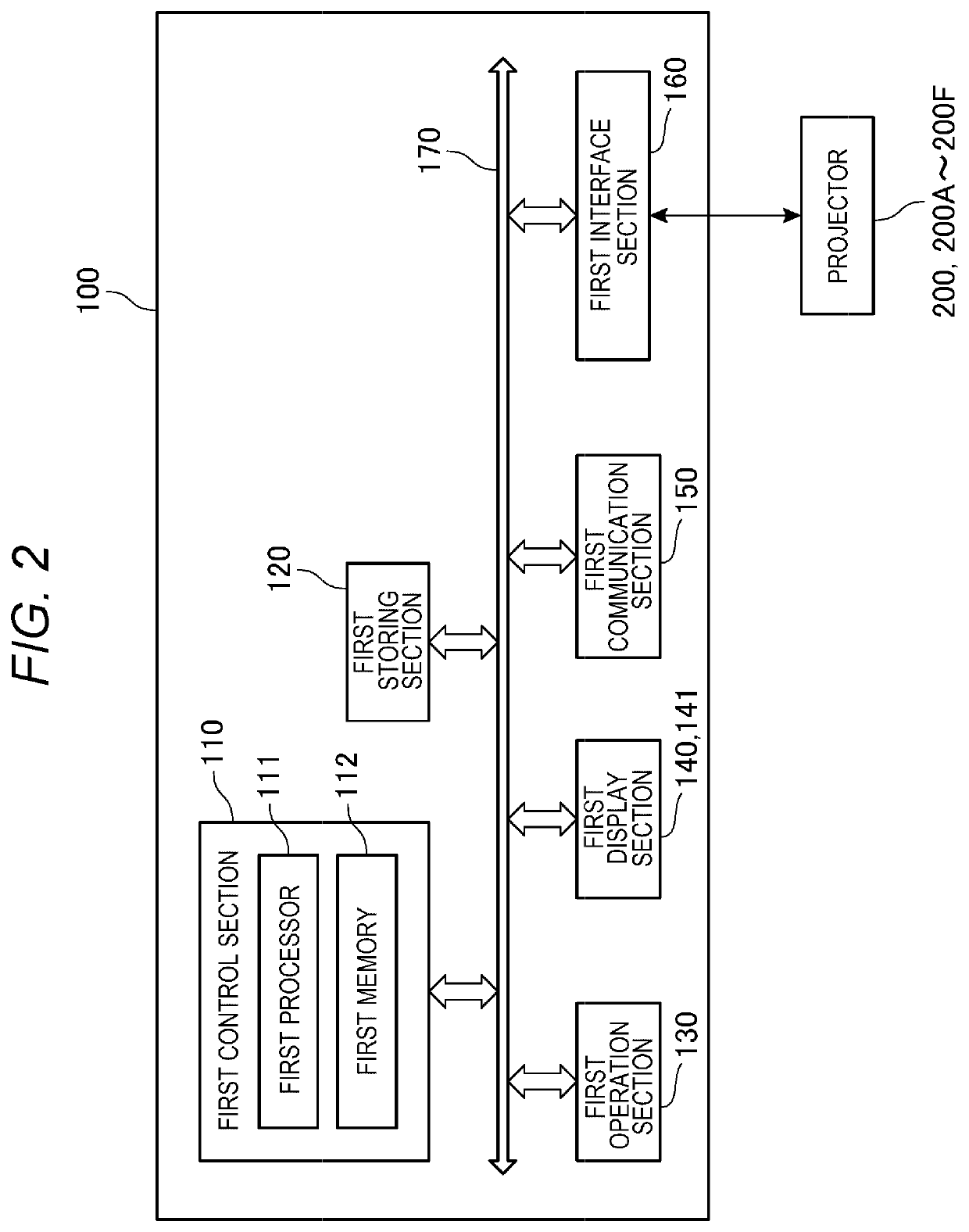
[0029]The image projection system 1 in this embodiment includes a control device 100 and a plurality of projectors 200. The control device 100 and the respective plurality of projectors 200 are communicably coupled via a network NW. The network NW is, for example, a LAN (Local Area Network). Communication is executed according to the Ethernet (registered trademark) standard.

[0030]The image projection system 1 includes, as the plurality of projectors 200, a first projector 200A, a second projector 200B, a third projector 200C, a fourth projector 200D, a fifth projector 200E, and a sixth projector 200F.

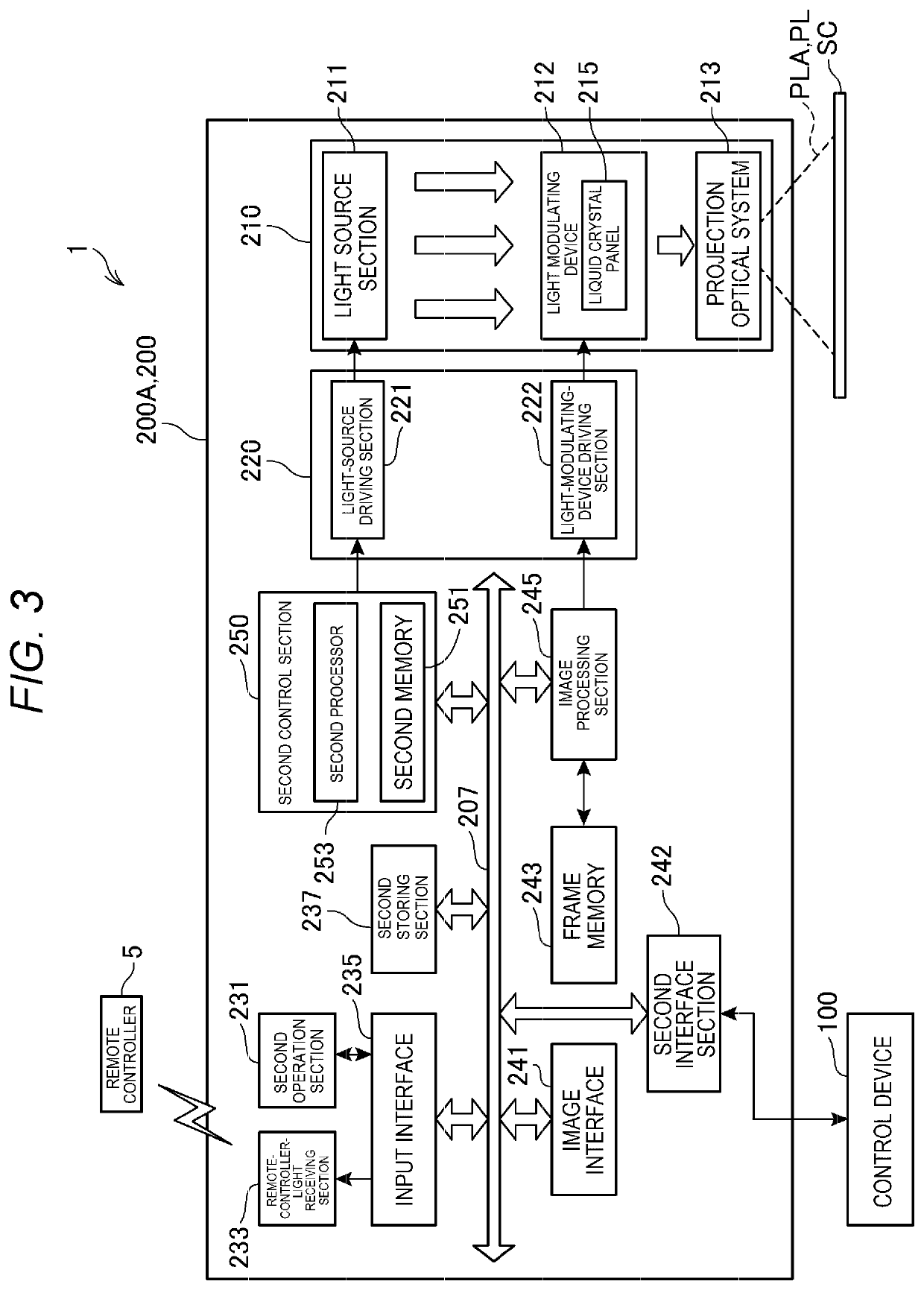
[0031]The respective first to sixth projectors 200A to 200F have substantially the same configurations.

[0032]In the fo...


PUM


Abstract

A control method for an image projection system including a plurality of projectors includes a determining step of determining, based on a stack number indicating the number of the projectors, projected images of which are superimposed one another, colors of pattern images projected by the respective projectors equivalent to the stack number and a projecting step of causing the respective projectors equivalent to the stack number to project the pattern images having the colors determined in the determining step. In the determining step, when the pattern images equivalent to the stack number are superimposed, the colors of the pattern images projected by the respective projectors equivalent to the stack number are determined such that the superimposed pattern images equivalent to the stack number have a specific color.

Description

[0001]The present application is based on, and claims priority from JP Application Serial Number 2019-139368, filed Jul. 30, 2019, the disclosure of which is hereby incorporated by reference herein in its entirety.BACKGROUND1. Technical Field[0002]The present disclosure relates to a control method for an image projection system and the image projection system.2. Related Art[0003]There has been known a technique concerning a method of correcting positions of projected images projected by a plurality of projectors that superimposes projected images one another (see, for example, JP-A-2006-245737 (Patent Literature 1)).[0004]A projected image correction device described in Patent Literature 1 includes first and second projecting means for projecting images onto the same projection surface, imaging means for photographing images on the projection surface, first instructing means for instructing the first and second projecting means to respectively project test images onto the projection...

Claims


Application Information

Patent Timeline
IPC IPC(8): H04N9/31
CPCH04N9/3147H04N9/3185H04N9/3105H04N9/3126H04N9/3188H04N9/3182
Inventor KUDO, YUSUKEKIHARA, HIROHIKO
Owner SEIKO EPSON CORP
Learn More