Dispensing tip holder
a technology for dispensing tips and pipettes, which is applied in the field of dispensing tip holders, can solve the problems of not being able to attach the dispensing tip to the pipette tip easily and reliably, and achieve the effect of easy and reliable attachmen
- Summary
- Abstract
- Description
- Claims
- Application Information
AI Technical Summary
Benefits of technology
Problems solved by technology
Method used
Image
Examples
first embodiment
(1) Dispensing Tip Holder
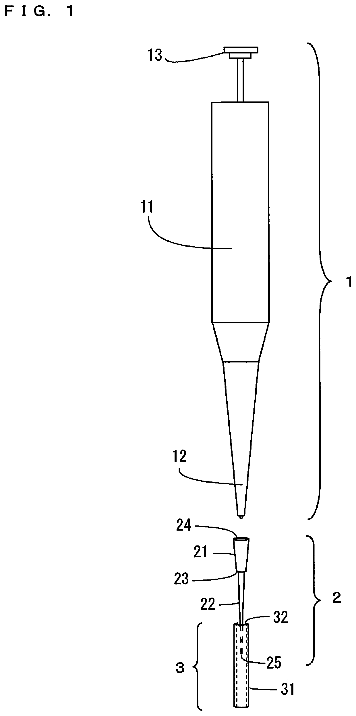
[0015]FIG. 1 is a schematic diagram showing a pipette, a dispensing tip, and a dispensing tip holder according to a first embodiment, which are used for a dispensing work.
[0016]The pipette 1 of FIG. 1 has a pipette body 11, a nose cone 12 and a push button 13. A piston rod and a piston rod drive mechanism are stored in the pipette body 11. The nose cone 12 has a truncated cone shape. The dispensing tip 2 is attached to the nose cone 12. The piston rod drive mechanism moves the piston rod in an up-and-down direction by an operation of the push button 13. Thus, a liquid sample is sucked into the dispensing tip 2 attached to the nose cone 12, or the liquid sample in the dispensing tip 2 is discharged.
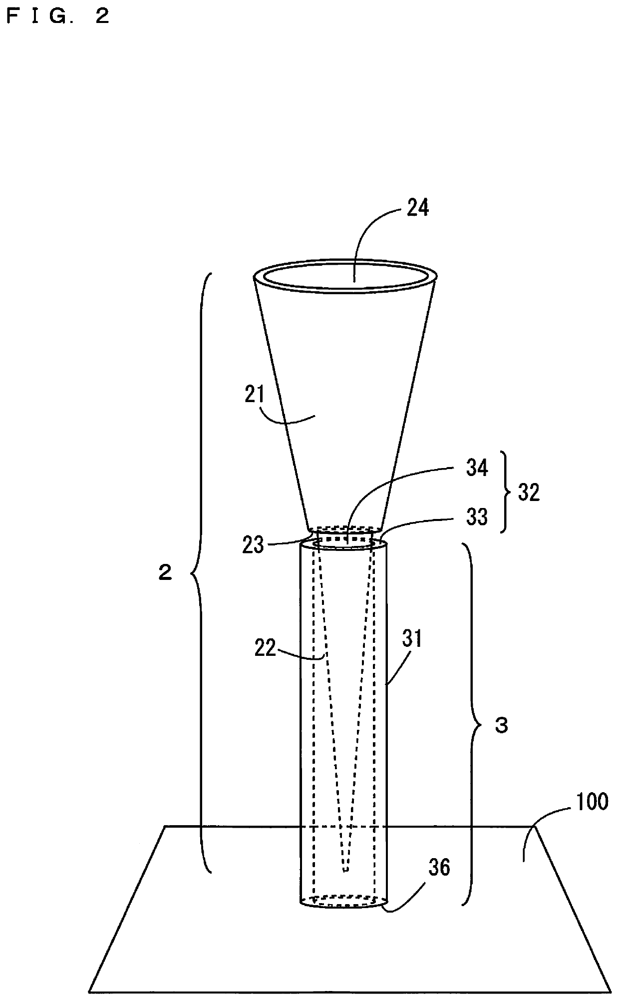
[0017]The dispensing tip 2 has a holder 21 having a truncated cone shape and a main body 22 having a cone shape. The upper end of the main body 22 is formed integrally with the lower end of the holder 21. The outer diameter of the upper end of the main body 22 is s...
second embodiment
(2) Dispensing Tip Holder
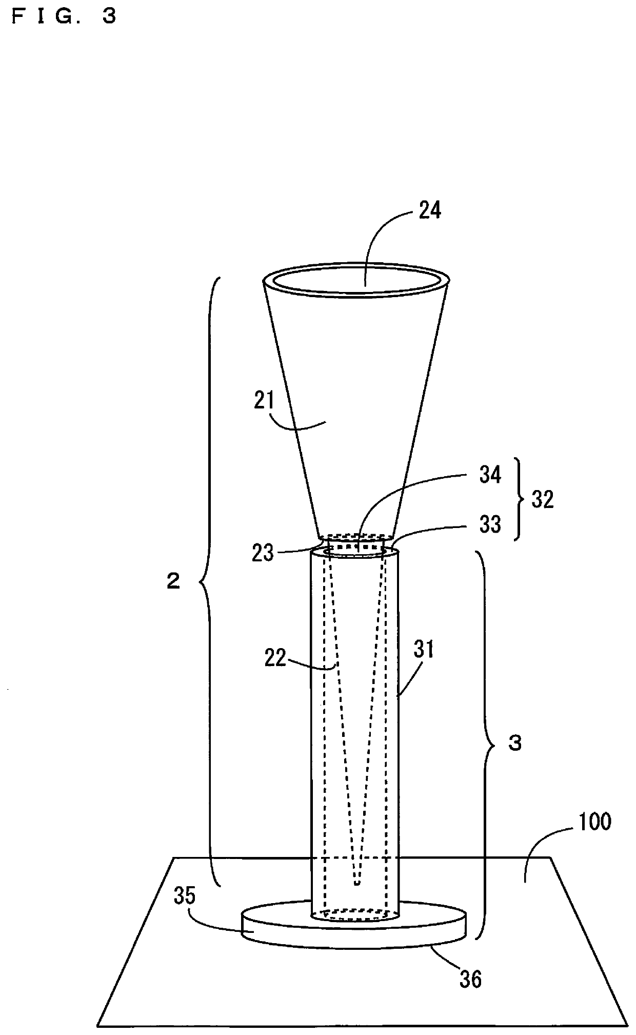
[0023]FIG. 3 is a perspective view showing a dispensing tip holder according to a second embodiment. The dispensing tip holder 3 of FIG. 3 is different from the dispensing tip holder 3 of FIG. 2 in the following point. In the dispensing tip holder 3 of FIG. 3, a circular base 35 is attached to the lower end surface of the peripheral wall 31. In the present embodiment, the lower surface of the base 35 is the support surface 36. The base 35 is formed to project outwardly from the peripheral wall 31. The shape of the base 35 is not limited to a circle but may be a polygon such as a square or another shape such as an oval. The configuration of the other parts of the dispensing tip holder 3 of FIG. 3 is similar to the configuration of the corresponding parts of the dispensing tip holder 3 of FIG. 2.
[0024]With the dispensing tip holder 3 according to the present embodiment, the peripheral wall 31 stands up more stably on the fixed surface 100. Therefore, the user ...
third embodiment
(3) Dispensing Tip Holder
[0025]FIG. 4 is a cross sectional view showing a dispensing tip holder according to a third embodiment. The dispensing tip holder 3 of FIG. 4 includes a cylindrical peripheral wall 31 and a plate-shaped insertion portion 32. A circular upper end opening is formed at the upper end of the peripheral wall 31. Further, a bottom portion 37 is formed at the lower end of the peripheral wall 31. In the present embodiment, the lower surface of the bottom portion 37 is the support surface 36.
[0026]An insertion portion 32 is formed at a position spaced apart from the upper end of the peripheral wall 31 by a predetermined distance in the peripheral wall 31. Further, the insertion portion 32 is provided at the height such that the distance from the bottom portion 37 to the insertion portion 32 is larger than the length of the main body 22 of the dispensing tip 2. A circular insertion opening 34 is formed in the center portion of the insertion portion 32. Thus, the insert...
PUM
| Property | Measurement | Unit |
|---|---|---|
| force | aaaaa | aaaaa |
| cone shape | aaaaa | aaaaa |
| shape | aaaaa | aaaaa |
Abstract
Description
Claims
Application Information
 - R&D Engineer
- R&D Manager
- IP Professional
- Industry Leading Data Capabilities
- Powerful AI technology
- Patent DNA Extraction
Browse by: Latest US Patents, China's latest patents, Technical Efficacy Thesaurus, Application Domain, Technology Topic, Popular Technical Reports.
© 2024 PatSnap. All rights reserved.Legal|Privacy policy|Modern Slavery Act Transparency Statement|Sitemap|About US| Contact US: help@patsnap.com


