
Hair styling device, hair styling method and drive system

a technology of hair waving device and hair styling method, which is applied in the direction of curling-tongs, curling-irons, hair equipments, etc., can solve the problems of reducing the likelihood of damage and increasing the likelihood of hair damage, so as to reduce the likelihood of user being burned, reduce the loss of wave, and be quick to style

Pending Publication Date: 2021-01-28
HD3
View PDF1 Cites 2 Cited by
  • Summary
  • Abstract
  • Description
  • Claims
  • Application Information

AI Technical Summary

Benefits of technology

The present invention is about a new hair styling device that avoids clamping the hair between heated plates, which leads to natural-looking waves and less damage to the hair. The device has two alternative drive systems that move all the driving rails sequentially and secure them in their limit positions. A second motor is used to drive the initiating element of the first driving rail and also act as the latch release mechanism for the driving rails. The use of a single motor reduces weight and cost of the device, but it is not limited to the specific drive systems or motor number discussed in the patent.

Problems solved by technology

Also, the likelihood of damage to hair is known to increase if the hair is heated to a styling temperature and clamped at the same time, so the avoidance of any clamping significantly reduces the likelihood of damage.

Method used


Image

  • Hair styling device, hair styling method and drive system
  • Hair styling device, hair styling method and drive system
  • Hair styling device, hair styling method and drive system

Examples


first embodiment

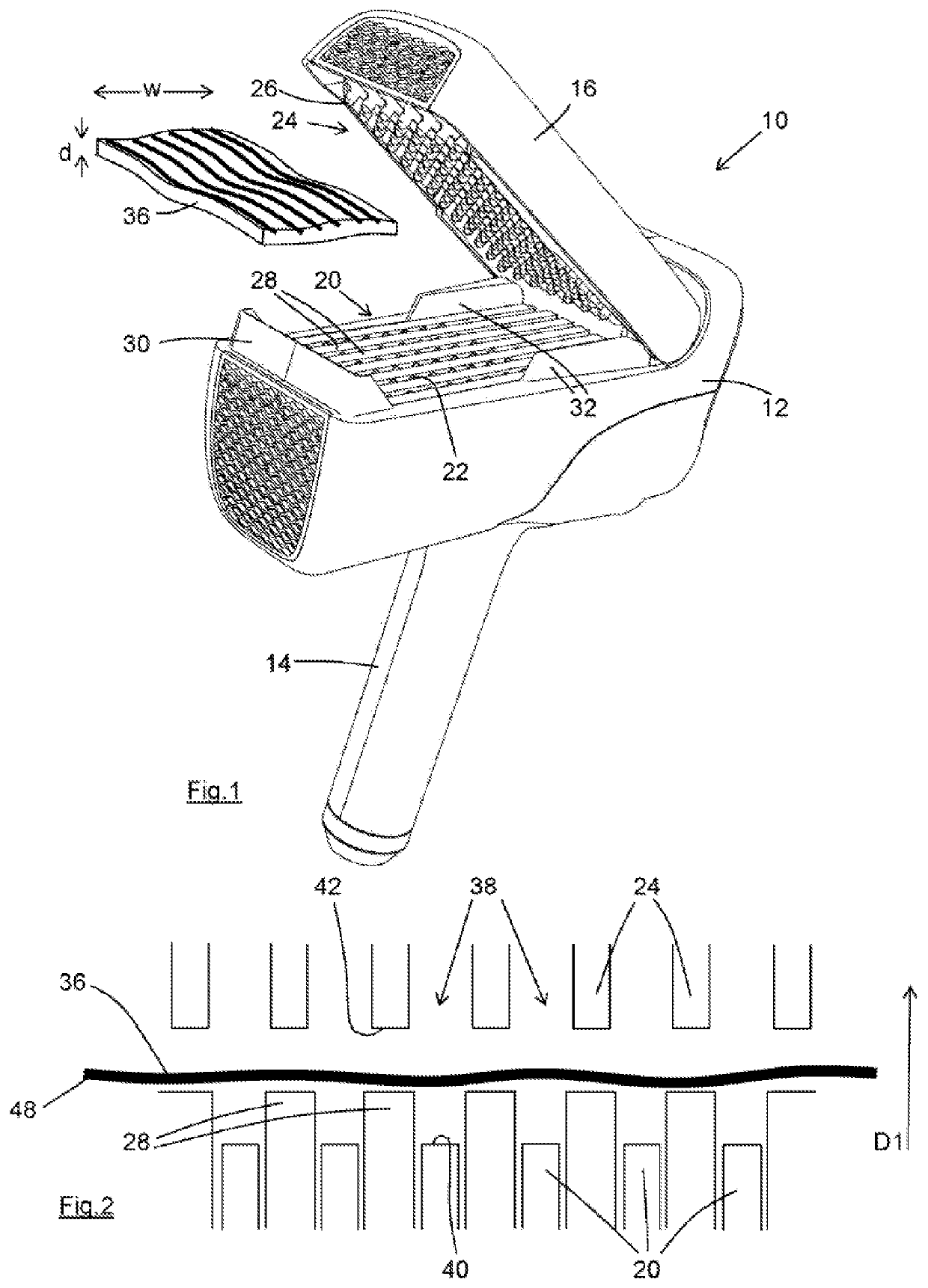
[0070]FIG. 1 shows a perspective view of hair styling device according to the present invention, in its open condition;

[0071]FIG. 2 represents the forming rails and driving rails of the device shown in FIG. 1;

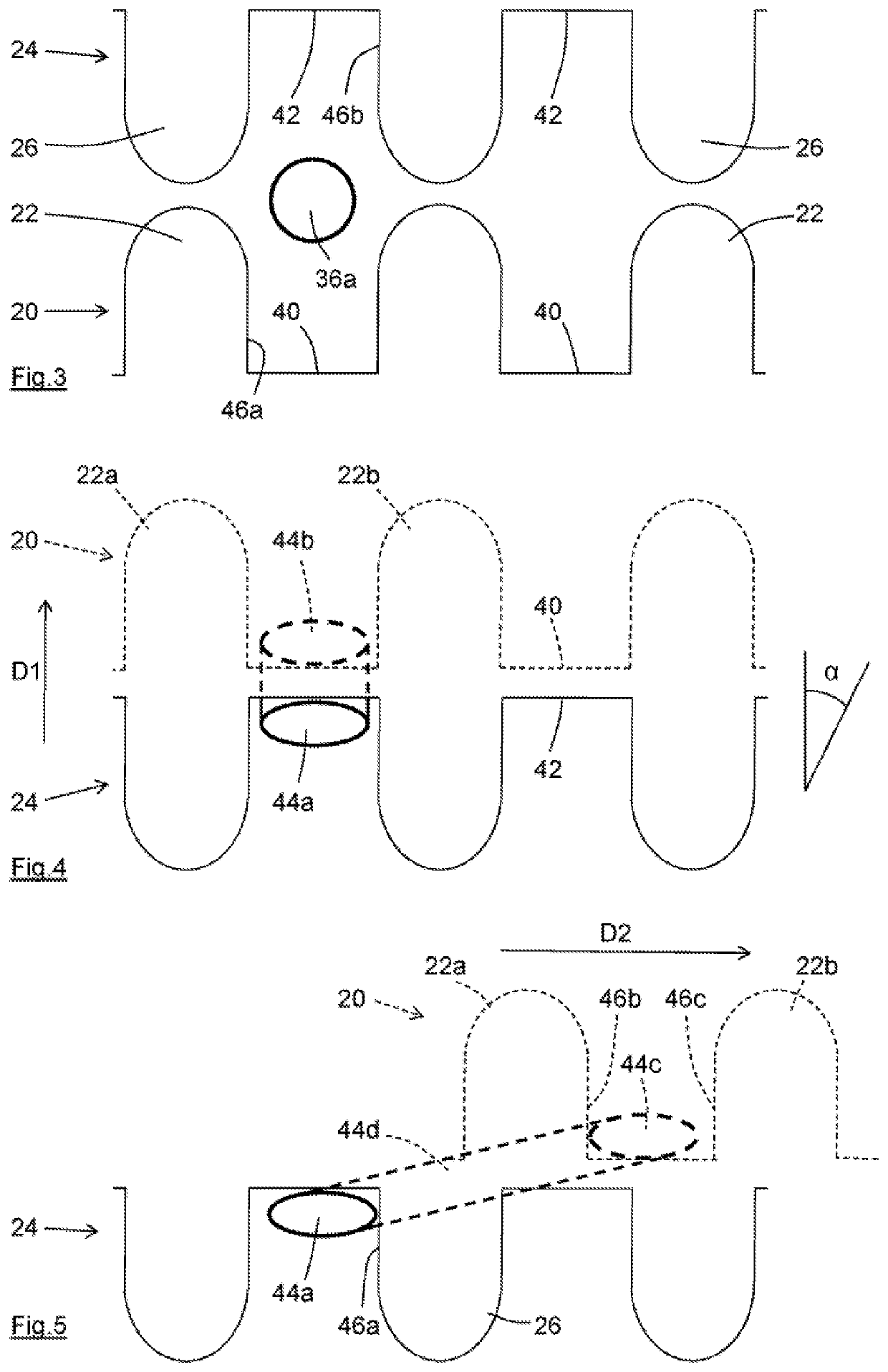
[0072]FIGS. 3-5 represent the sequence of operations for the driving rails and forming rails for the purpose of explaining the operation of the device of FIG. 1;

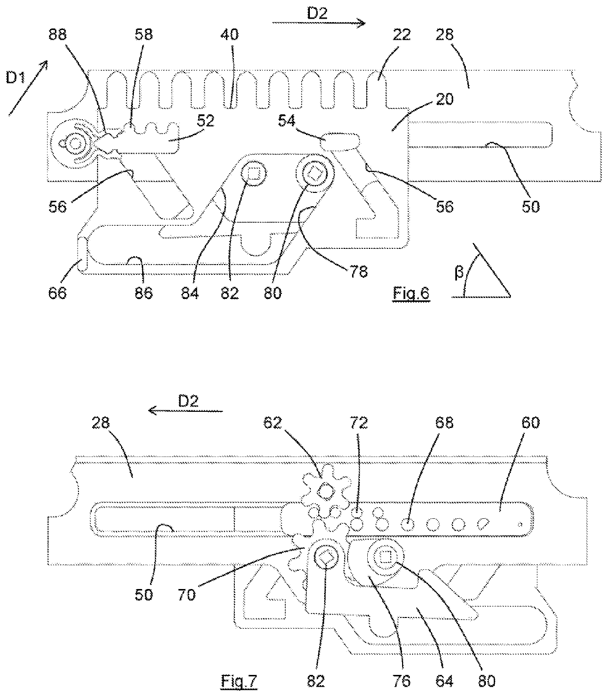
[0073]FIG. 6 shows a side view of a first embodiment of one of the drive mechanisms of the device of FIG. 1, in its start or rest position;

[0074]FIG. 7 shows the opposing side view of the drive mechanism of FIG. 6;

[0075]FIG. 8 shows a side view of the device of FIG. 1, with one of the driving rails in its limit position and another of the driving rails part-way through its movement in the first direction;

[0076]FIG. 9 shows a view as FIG. 8, with all of the driving rails at their limit positions;

[0077]FIG. 10 shows a view as FIG. 9, with all of the driving rails moved back to their retracted positions;

second embodiment

[0078]FIG. 11 shows a view similar to that of FIG. 6 of drive mechanism;

[0079]FIG. 12 shows the drive mechanism of FIG. 11 with the driving rail in its limit position;

[0080]FIG. 13 shows the latch of the second embodiment of drive mechanism;

[0081]FIG. 14 shows a view of the second embodiment of drive mechanism of FIG. 11 from the opposing side;

[0082]FIG. 15 shows a view of the second embodiment of drive mechanism of FIG. 12 from the opposing side;

[0083]FIG. 16 shows a perspective view of a second embodiment of hair styling device according to the present invention, in its open condition;

[0084]FIG. 17 shows the drive mechanisms of the second embodiment of hair styling device, with all of the driving rails in their start positions; and

[0085]FIG. 18 shows a view as FIG. 17 but with the first driving rail part-way through its range of movement.


PUM


Abstract

This invention relates to a hair styling device, a hair styling method, and a drive system suitable for use in the hair styling device. The invention relates in particular to a hair styling device (10; 210) for imparting a wave to a section of hair (36) without clamping the section of hair in the wave form. The device has a first forming member (24) and a second forming member (24) with a hair-receiving region (38) between the forming members. A driving member (20; 120) is movable relative to the first forming member and the second forming member to deform the section of hair in the hair-receiving region. The driving member (20; 120) undertakes a two-stage movement as it deforms the section of hair, the driving member in a first stage being movable in a first direction (D1) to drive the section of hair (36) into the hair-receiving region, the driving member (20; 120) in a second stage being movable in a second direction (D2), the second direction being at an angle to the first direction whereby in use to further move the section of hair in the hair-receiving region (38).

Description

FIELD OF THE INVENTION[0001]This invention relates to a hair styling device, to a hair styling method, and to a drive system suitable for use in the hair styling device. The invention relates in particular to a hair waving device.BACKGROUND TO THE INVENTION[0002]A hair styling device is described in WO95 / 22920, by one of the present inventors. WO95 / 22920 discloses a method of styling a section (or length) of hair by inserting the section of hair into a resilient tube of latex or the like, the tube being stretched lengthwise and the ends of the tube being secured to respective parts of the section of hair. The resilient tube is allowed to contract whereupon the contained section of hair is forced into a wavy form. The hair can be treated before or after insertion into the tube so that the wavy form is maintained after the hair has been removed from the tube.[0003]WO95 / 22920 also describes a device for use in the method. Improved devices for use in similar hair styling methods are des...

Claims


Application Information

Patent Timeline
Patent Type & Authority Applications(United States)
IPC IPC(8): A45D1/04A45D2/40
CPCA45D1/04A45D2001/004A45D2/40A45D1/02A45D2/2457A45D2/44A45D1/00A45D2001/002
Inventor DEBENEDICTIS, ALFREDOHARRIS, MARTIN MALCOLMHOLLAND, JANUSZ LUCIENHUGHES, MARK CHRISTOPHERNELSON, JAMES ROBERT
Owner HD3
Learn More