Warning system for detecting approaching object and method thereof

Active Publication Date: 2021-01-21
CUBTEK INC
View PDF0 Cites 0 Cited by
  • Summary
  • Abstract
  • Description
  • Claims
  • Application Information

AI Technical Summary

Benefits of technology

The invention aims to prevent accidents by detecting approaching objects in a control area and confirming their movement. The invention checks the object's movement and confirm it to be continuous in the warning area. If confirmed, the invention sends a warning signal to the control area to stop the approaching object to prevent collisions with the train and avoid accidents. This technology prevents panicking or fear among people at the scene caused by incorrect identification of objects.

Problems solved by technology

As a result, the people at the scene will misjudge the approaching object as a dangerous vehicle for the driving, further causing fear or panic.
However, regarding such conventional image detection system, besides the possibility of misidentification under a poor vision, if there are no vehicles or people lingering in the control area but there are approaching objects, people or animals heading toward the control area, the conventional image detection system is unable to detect and send out the warning for immediately stopping the train from entering the control area.

Method used


Image

  • Warning system for detecting approaching object and method thereof
  • Warning system for detecting approaching object and method thereof
  • Warning system for detecting approaching object and method thereof

Examples


second embodiment

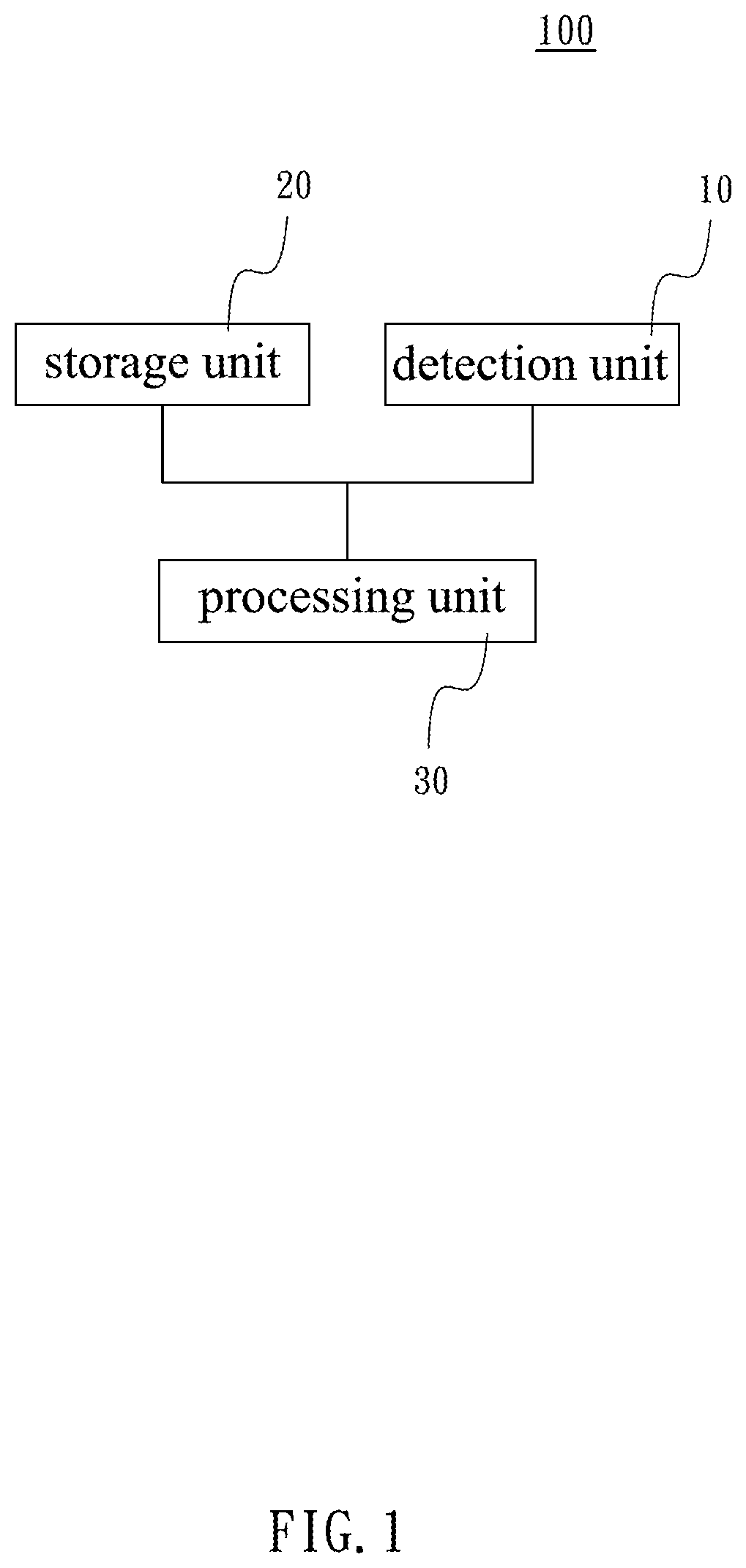
[0046]Also referring to FIG. 8 to FIG. 14 in view of FIG. 2 and FIG. 5, the warning system 100 in accordance with the present invention is illustrated. In the embodiment, the warning system 100 is disposed in a control area CA at the intersection of a rail R1 and a road R2. The warning system 100 comprises a plurality of detection units 10, a storage unit 20, and a processing unit 30. For facilitating the purpose of illustration, the control area CA in the embodiment is shown by a square shape area defined by the intersection of the rail R1 and a road R2. However, the scope of the control area CA is not limited by the square shape area herein. In the following embodiment, the approaching object V detected by the warning system 100 is, for example but not limited to, a moving vehicle. In other words, any objects that are approaching the warning system 100 can be considered as the target of detection, such as pedestrians or animals (such as cats and dogs).

[0047]In the embodiment, the ...

first embodiment

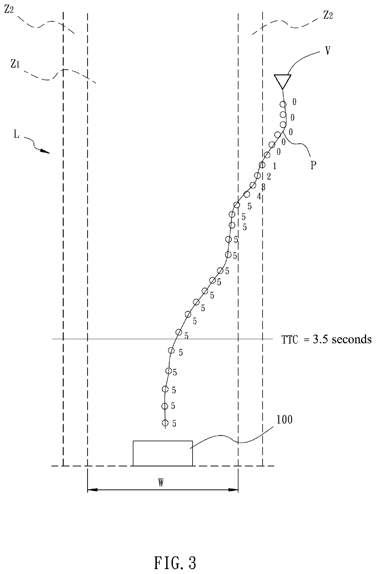
[0052]In the embodiment, the horizontal radars 11 of a plurality of detection units 10 detect a moving path P of an approaching object V moving toward the control area CA along the road R2, and the moving path P is transformed into a detection signal to be outputted. The storage unit 20, as in the first embodiment, is applied for storing the warning information, which also comprises the warning area L and the confirmation condition. The warning area L is set in the detection area. The confirmation condition is for confirming that the approaching object V is continuously moving in the warning area L. The processing unit 30 is electrically connected with the detection unit 10 and the storage unit 20 for receiving the detection signal outputted by the detection unit 10, so as to acquire the real-time moving path P of the approaching object V.

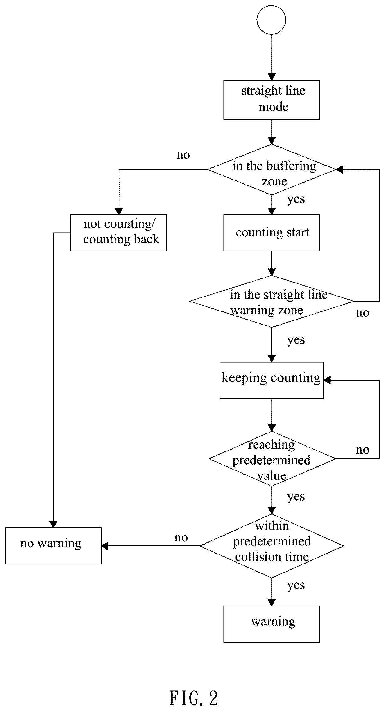
[0053]In the embodiment, the confirmation is the same as in the first embodiment. The predetermined count value is also 5, and the current count v...


PUM


Abstract

A warning system for detecting approaching object and method thereof are provided. A detection unit detects a moving path of the approaching object; a storage unit stores a warning information including the warning area and the confirmation condition; and a processing unit receives the detection signal provided by the detection unit to acquire the current moving path of the approaching object. When the approaching object is detected as moving in the buffering zone, the confirmation operation of the confirmation condition is activated. When the moving path falls in the warning area and fulfills the confirmation condition, the processing unit sends out a warning signal. Therefore, a potentially dangerous approaching object is accurately identified, and the warning is correctly sent.

Description

CROSS REFERENCE TO RELATED APPLICATIONS[0001]This application is a Continuation-in-Part of co-pending application Ser. No. 16 / 287,205, filed on 27 Feb. 2019, for which priority is claimed under 35 U.S.C. § 120, the entire contents of all of which are hereby incorporated by reference.BACKGROUND OF THE INVENTION1. Field of the Invention[0002]The present invention relates to warning systems, and more particularly, to a warning system for detecting approaching object and method thereof.2. Description of the Related Art[0003]A conventional detection warning system is statically placed for preventing the collision caused by other approaching objects. The radar detects the speed or distance of an approaching object, thereby determining if the approaching object is a potentially dangerous vehicle. However, when the approaching speed or distance of the approaching object reaches a predetermined range, the alarm will be sounded even if the approaching object moves away toward other directions...

Claims


Application Information

Patent Timeline
IPC IPC(8): B61L23/04B61L23/34G01S13/931
CPCB61L23/041G01S2013/9328G01S13/931B61L23/34B60Q9/008B60W30/0956B60W50/14B60W2050/143B60W2554/802G01S13/91G01S13/72B61L29/30
Inventor LIN, JYONGLIN, YU-JENSYU, GUO-HAOCHU, CHIA-CHUN
Owner CUBTEK INC
Why Eureka
Try Eureka