Storage tank for pressurized gas and method of manufacturing same

a technology of gas storage tank and pressurized gas, which is applied in the direction of vessel geometry/arrangement/size, mechanical equipment, vessel construction details, etc., can solve the problems of temperature drop, gas trapped, other less desirable options for avoiding the issue of trapped gas need not be implemented, etc., to facilitate the removal of trapped permeated gas, reduce gas permeation, and reduce the range of vehicles

Active Publication Date: 2021-01-14
GM GLOBAL TECH OPERATIONS LLC
View PDF0 Cites 5 Cited by
  • Summary
  • Abstract
  • Description
  • Claims
  • Application Information

AI Technical Summary

Benefits of technology

The patent text describes a storage tank for pressurized gas that includes a nanoporous carbon shell. The carbon shell helps to remove trapped gas molecules that may accumulate during use of the gas. The nanopores in the carbon shell are small enough to prevent resin molecules from entering the tank, while still allowing gas molecules to pass through. The carbon fiber reinforced polymer layer also prevents resin molecules from entering until the layer is heated and cured. The storage tank design also includes bosses that further enclose the interior cavity of the tank for added protection. The technical effect of this design is to improve gas storage and minimize trapped gas, which can lead to reduced efficiency and increased weight of the storage tank.

Problems solved by technology

As the gas in the interior cavity is used and the interior cavity depressurizes, a resulting temperature drop occurs.
Different thermal expansion coefficients of the materials of the storage tank and / or a rapid depressurization of the tank may lead to the permeated gas being trapped between an inner liner of the tank and a surrounding carbon reinforced polymer layer.
Accordingly, other less desirable options for avoiding the issue of trapped gas need not be implemented.
For example, increasing the minimum pressure in the tank would reduce gas permeation, but would also decrease vehicle range.
However, given the ability of the permeated gas to diffuse through the nanoporous carbon shell and exit from the storage tank at the exposed surface (or surfaces) of the nanoporous carbon shell, inward buckling of the liner may be infrequent or nonexistent in any event.
When heated, a PVDC polymer produces hydrogen chloride gas, which is corrosive to steel.

Method used


Image

  • Storage tank for pressurized gas and method of manufacturing same
  • Storage tank for pressurized gas and method of manufacturing same
  • Storage tank for pressurized gas and method of manufacturing same

Examples


Embodiment Construction

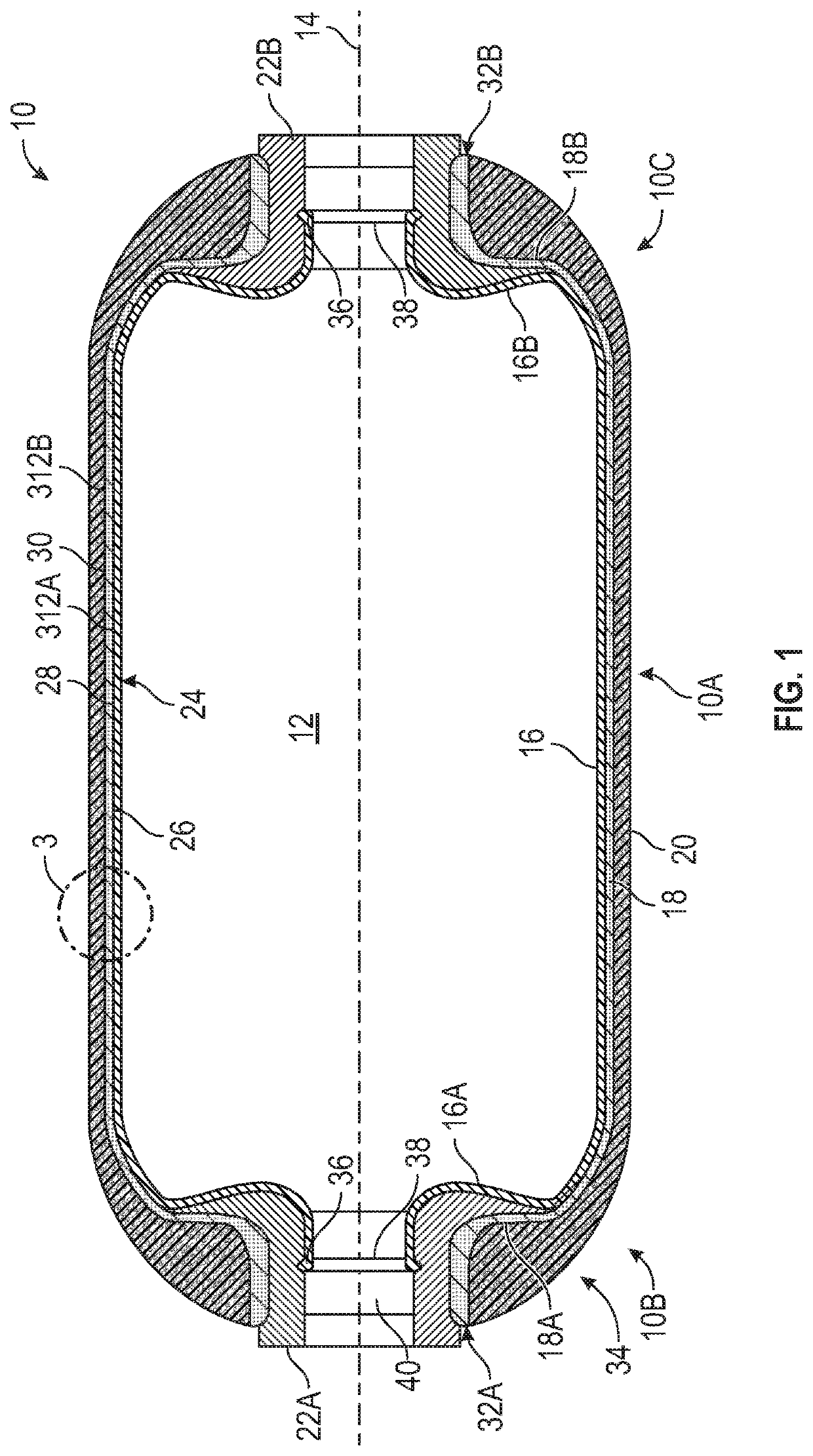
[0028]FIG. 1 is a cross-sectional view of a gas storage tank 10 according to aspects of the present disclosure. As shown, the gas storage tank 10 includes a generally elongated cylindrical middle portion 10A, a first end portion 10B, and an opposing second end portion 10C surrounding an interior cavity 12 and spaced along a longitudinal axis 14. In other embodiments, the gas storage tank 10 may have other shapes. In a direction outward from the interior cavity 12, the storage tank 10 includes a liner 16, a nanoporous carbon shell 18, and a carbon fiber reinforced polymer layer 20. Bosses 22A, 22B are installed on one or both end portions 10B, 10C as discussed herein, and may be plugged or house a valve (not shown) for accessing the pressurized gas. The gas storage tank 10 may or may not also include a glass overwrap around the outer surface of the carbon fiber reinforced polymer layer 20, foam caps over the domed end portions 10B, 10C, and other components and features. The gas stor...


PUM

PropertyMeasurementUnit
Pressureaaaaaaaaaa
Pressureaaaaaaaaaa
Widthaaaaaaaaaa

Abstract

A storage tank for pressurized gas includes a liner defining an interior cavity for storing the pressurized gas. The storage tank further includes a nanoporous carbon shell formed from at least one pyrolyzed polymer. The liner is disposed at an inner side of the nanoporous carbon shell. The storage tank further includes a carbon fiber reinforced polymer layer disposed on an outer side of the nanoporous carbon shell opposite from the liner. The nanoporous carbon shell has an exposed surface at an exterior of the storage tank and is configured to permit gas permeated through the liner from the interior cavity to diffuse through the nanoporous carbon shell to the exposed surface.

Description

INTRODUCTION[0001]The disclosure relates to gas storage tanks. More specifically, the disclosure relates to gas storage tanks having a pyrolyzed carbon shell for releasing permeated gas, and to methods of manufacturing such storage tanks.[0002]Tanks for storing pressurized gas may have multiple layers, including layers configured to seal the gas, and other layers configured to increase strength and durability. Considerations in designing such tanks include compatibility of materials, weight, and ease of manufacturing. Gas storage tanks used on vehicles, such as those used to store hydrogen gas on a fuel cell vehicle, may experience permeation of hydrogen gas molecules into one or more of the layers during defueling due to a temperature drop in the tank associated with the decrease in gas pressure.SUMMARY[0003]A storage tank for pressurized gas includes a nanoporous carbon shell that facilitates the removal of trapped permeated gas. When pressurized gas in the storage tank is at rela...

Claims


Application Information

Patent Timeline
IPC IPC(8): F17C1/16
CPCF17C1/16F17C2201/0109F17C2205/0305F17C2203/0604F17C2209/2163F17C2223/0123F17C2203/0673F17C2223/036F17C2203/0621F17C2221/012F17C1/06F17C2201/0104F17C2201/056F17C2203/066F17C2203/0663F17C2260/037F17C2270/0168Y02E60/32
Inventor BECKNER, MATTHEW
Owner GM GLOBAL TECH OPERATIONS LLC
Why Eureka
Try Eureka