Core main body, reactor, and method of manufacturing reactor

a technology of reactors and main bodies, applied in the direction of transformers/inductances magnetic cores, magnetic core manufacturing, cores/yokes, etc., can solve the problems of lowering workability during transport and during, and achieve the effect of lowering workability and lowering workability

Active Publication Date: 2021-01-07
FANUC LTD
View PDF3 Cites 1 Cited by
  • Summary
  • Abstract
  • Description
  • Claims
  • Application Information

AI Technical Summary

Benefits of technology

[0004]However, because the end plate is attached to one end of a core main body, the end plate is positioned away from a center of gravity of the reactor. For this reason, there has been a problem that when the reactor is lifted up, the reactor is inclined, and as a result, workability is lowered during transport and during attachment on the vertical surface. In addition, in a case where only the core main body to which the end plate is attached is lifted up, the core main body is also inclined, so a similar problem occurs.
[0005]Therefore, a core main body and a reactor that do not lower workability during transport and attachment, and a manufacturing method of such a reactor are desired.

Problems solved by technology

For this reason, there has been a problem that when the reactor is lifted up, the reactor is inclined, and as a result, workability is lowered during transport and during attachment on the vertical surface.
In addition, in a case where only the core main body to which the end plate is attached is lifted up, the core main body is also inclined, so a similar problem occurs.

Method used


Image

  • Core main body, reactor, and method of manufacturing reactor
  • Core main body, reactor, and method of manufacturing reactor
  • Core main body, reactor, and method of manufacturing reactor

Examples


first embodiment

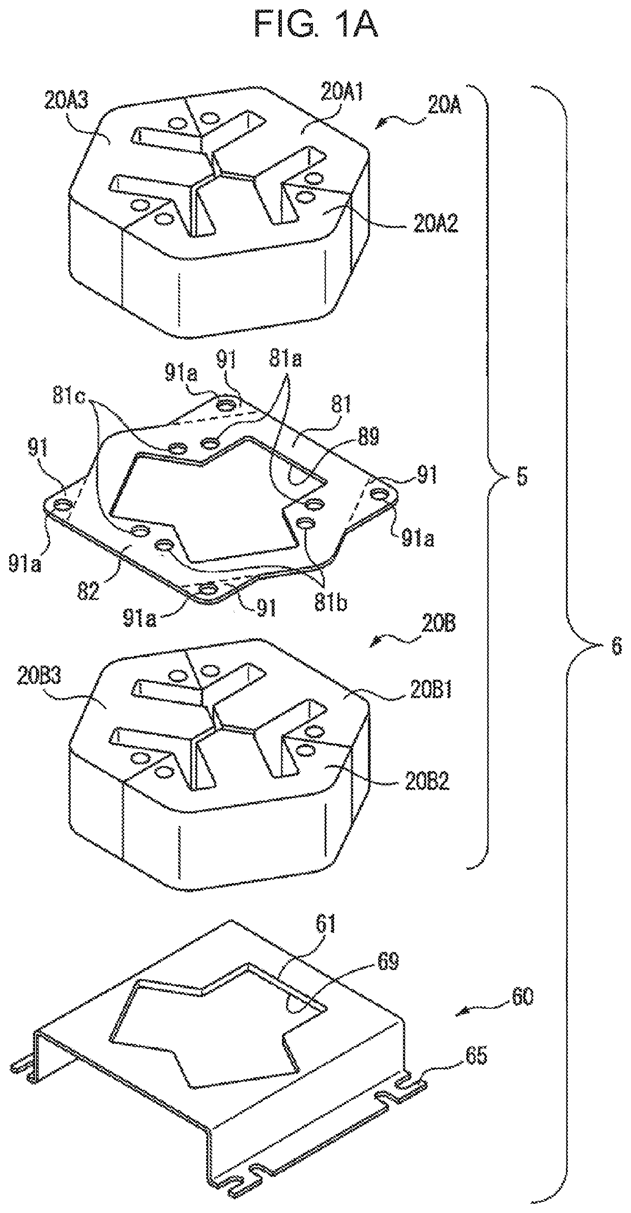
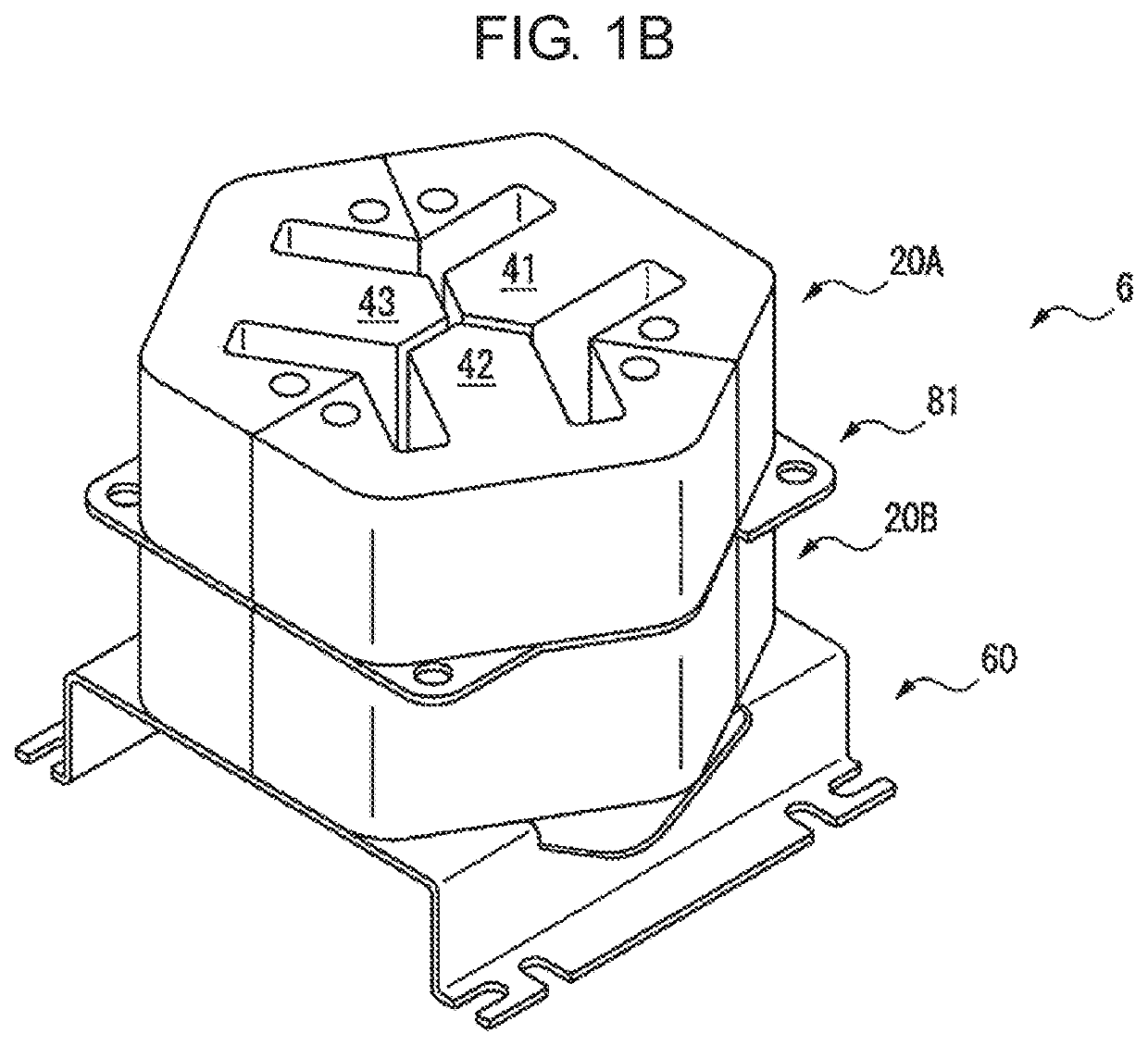
[0021]FIG. 1A is an exploded perspective view of the reactor and FIG. 1B is a perspective view of the reactor illustrated in FIG. 1A. A reactor 6 illustrated in FIG. 1A and FIG. 1B mainly includes a core main body 5 and a pedestal 60 attached to one end of the core main body 5.

[0022]The core main body 5 includes a first outer peripheral iron core block 20A, a second outer peripheral iron core block 20B, and an intermediate plate 81 sandwiched between the first outer peripheral iron core block 20A and the second outer peripheral iron core block 20B. Each of the first outer peripheral iron core block 20A and the second outer peripheral iron core block 20B is formed by stacking a plurality of magnetic plates, for example, an iron plate, a carbon steel plate, and an electromagnetic steel plate in an axial direction of the reactor 6. The magnetic plates used to form the first outer peripheral iron core block 20A and the magnetic plates used to form the second outer peripheral iron core ...

second embodiment

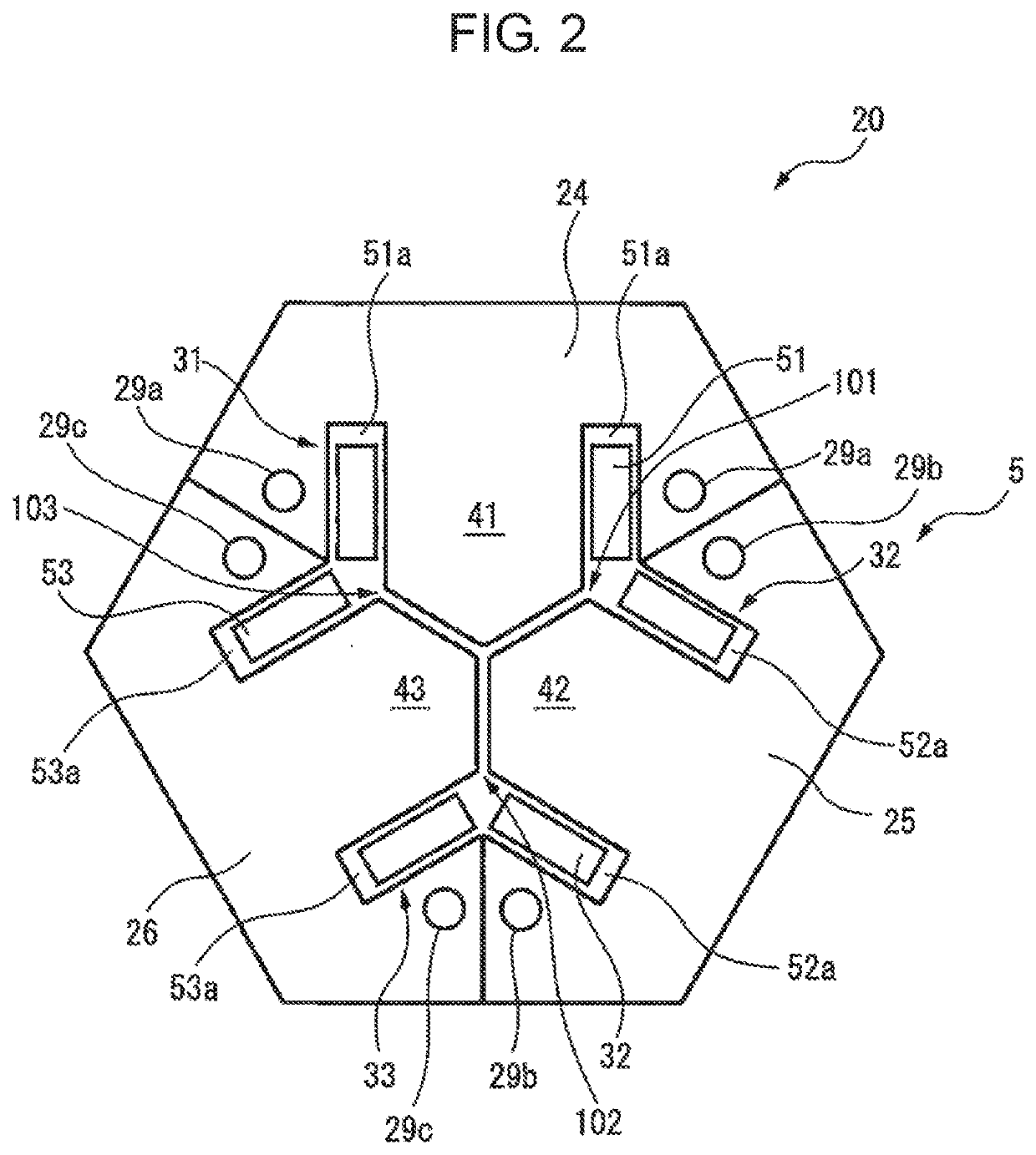
[0045]FIG. 6 is a cross-sectional view of a core main body of a reactor according to a The core main body 5 illustrated in FIG. 6 includes the outer peripheral iron core 20 whose cross section is a substantially octagonal shape, and four iron core coils 31 to 34, similar to those described above, disposed inside the outer peripheral iron core 20. These iron core coils 31 to 34 are arranged at equal intervals in a circumferential direction of the core main body 5. In addition, the number of iron cores is preferably an even number being equal to or more than four, and thus the reactor provided with the core main body 5 can be used as a single-phase reactor.

[0046]As can be seen from the drawings, the outer peripheral iron core 20 is formed of four outer peripheral iron core portions 24 to 27 that are circumferentially disposed. The iron core coils 31 to 34 respectively include the iron cores 41 to 44 extending only radially and the coils 51 to 54 mounted around the corresponding iron ...


PUM

PropertyMeasurementUnit
tip angleaaaaaaaaaa
tip angleaaaaaaaaaa
gravityaaaaaaaaaa

Abstract

A core main body includes an outer peripheral iron core, and at least three iron cores. Between the two iron cores adjacent to each other, a gap being magnetically couplable is formed. The outer peripheral iron core includes a first outer peripheral iron core block and a second outer peripheral iron core block that are formed by stacking a plurality of magnetic plates, and an intermediate plate disposed therebetween. The intermediate plate includes an outer peripheral iron core corresponding portion corresponding to the outer peripheral iron core, a plurality of protruding sections protruding from an outer peripheral surface of the outer peripheral iron core, and engaging sections provided on the plurality of protruding sections.

Description

BACKGROUND OF THE INVENTION1. Field of the Invention[0001]The present invention relates to a core main body, a reactor, and a method of manufacturing the reactor.2. Description of the Related Art[0002]In recent years, a reactor has been developed that is provided with a core main body including an outer peripheral iron core and a plurality of iron cores disposed inside the outer peripheral iron core. Each of the plurality of iron cores is mounted with a coil. The core main body of such a reactor is sandwiched between an end plate and a pedestal. For example, see Japanese Unexamined Patent Publication No. 2019-029449 A.SUMMARY OF THE INVENTION[0003]In general, a reactor is attached on a vertical surface, for example, a wall section of a power distribution board. In such a case, by inserting a wire or the like into an opening formed on a corner section of the end plate, the reactor is lifted up and transported to a desired location, and then a pedestal of the reactor is attached on th...

Claims


Application Information

Patent Timeline
Patent Type & Authority Applications(United States)
IPC IPC(8): H01F27/24H01F27/28H01F41/02
CPCH01F27/24H01F41/0206H01F27/28H01F3/14H01F27/245H01F27/263H01F27/306H01F41/0233H01F41/04H01F27/002H01F37/00
Inventor YOSHIDA, TOMOKAZU
Owner FANUC LTD
Why Eureka
Try Eureka