
Dental extraction device

a dental extraction and tooth extraction technology, applied in the field of dental extraction devices, can solve the problems of tooth extraction scarring to most patients, damage to the mouth, and complicated process, and achieve the effects of low cost, minimal tool, and low effor

Inactive Publication Date: 2020-12-24
LIU CHAO LIN
View PDF0 Cites 0 Cited by
  • Summary
  • Abstract
  • Description
  • Claims
  • Application Information

AI Technical Summary

Benefits of technology

The present invention is a dental extraction device that has a simple structure and is easy to operate. This device allows for tooth extraction with minimal damage to the surrounding tissues and requires fewer tools and extraction forces. Therefore, the technical effect of this invention is to make dental extraction more efficient and safe with reduced patient pain and recovery time.

Problems solved by technology

However, this is only applicable when there is a sufficient portion of a tooth crown left.
Such a process is obviously complicated and involves a number of dental extraction instruments.
Particularly, such a process often generates sounds and pains that might cause panics of patients, making tooth extraction scaring to most patients even in this modem world where the medical science has been well developed.
Although this prior art document claims a large extraction force can be applied to the root with a simple operation such that there is no need for a user to apply a large effort and no issue concerning space requirement would occur, and the potential risk of causing damage to the mouth can be reduced, the cost of fabrication or the sales prices are not affordable to the users, and such a device is only applicable to removal of tooth root, making the application thereof very limited, leading to extremely low cost-performance ratio.
(1) The fabrication cost or the sales price is high, making it adverse to popularization in the dental field.
(2) The use or application thereof is limited.
(3) A substantive amount of force must be applied to resist the tension device, making the operation of such a device not easy.

Method used


Image

  • Dental extraction device
  • Dental extraction device
  • Dental extraction device

Examples


Embodiment Construction

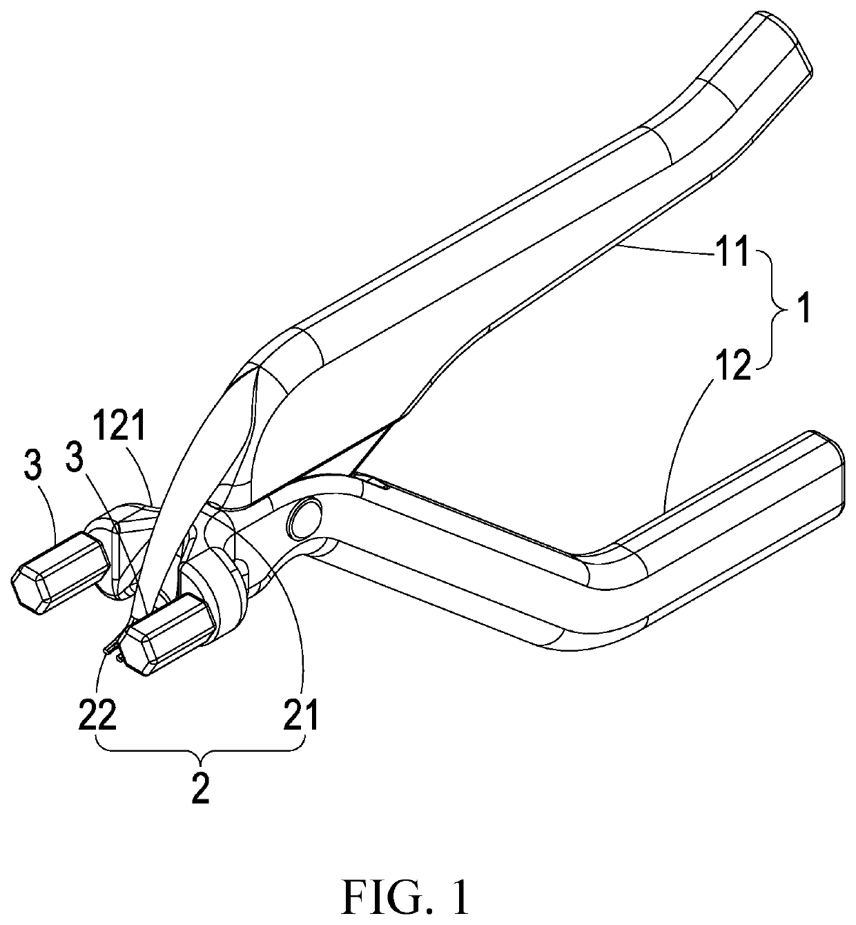
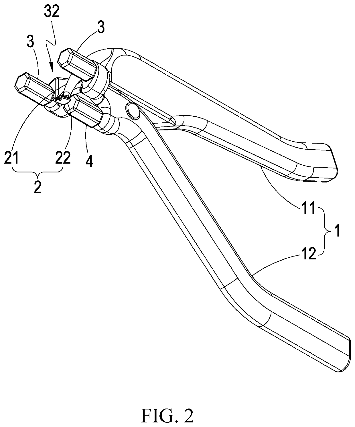
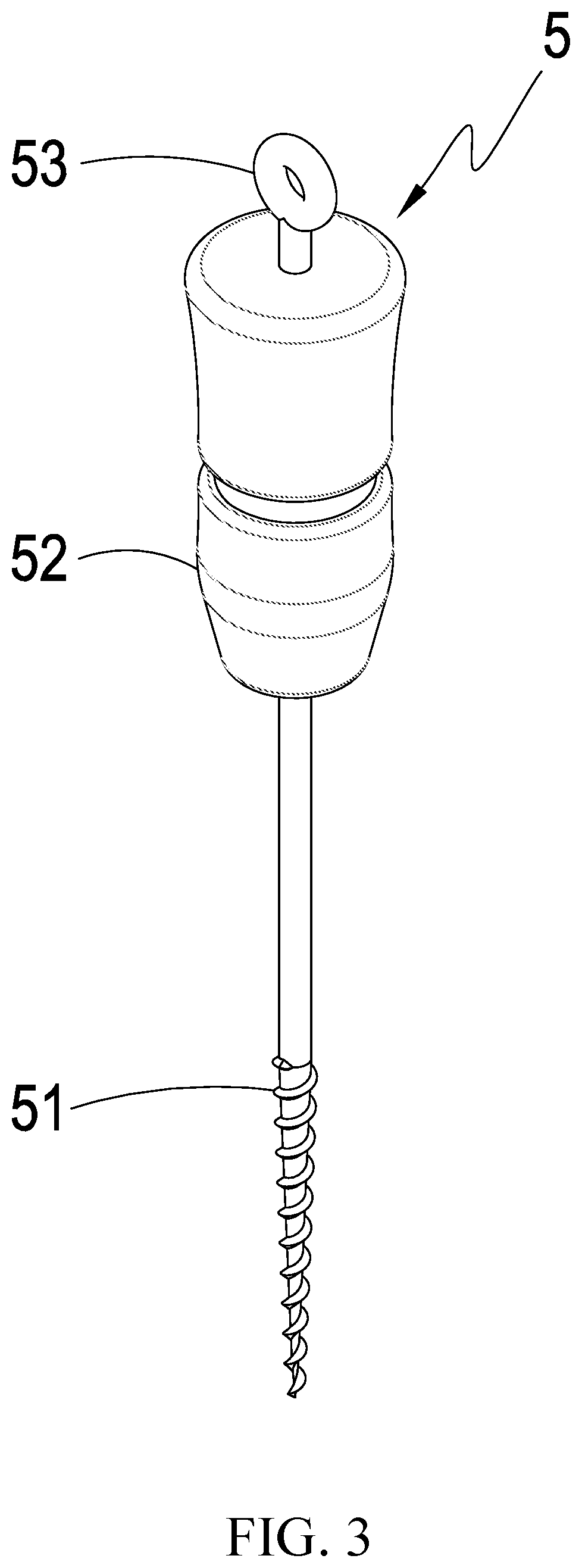
[0038]Referring to FIGS. 1-3, which are respectively a perspective view showing a first preferred embodiment of the present invention, another perspective view showing the first preferred embodiment of the present invention, and a perspective view showing a tooth holding member of the first preferred embodiment of the present invention, these drawing clearly show the present invention comprises:

[0039]a gripping assembly 1, the gripping assembly 1 comprising a first gripping arm 11 and a second gripping arm 12 pivoted on the first gripping arm 11;

[0040]a recess 121 formed on the second gripping arm 12 for receiving and accommodating a corner of a mouth;

[0041]a prying element 2 formed on one end of the first gripping arm 11, the prying element 2 comprising a driving arm 21 formed on one end of the first gripping arm 11, and an abutting and hooking portion 22 formed on one end of the driving arm 21, which is operatively cooperating with a tooth holding member 5 to extract a first tooth...


PUM


Abstract

A dental extraction device includes a gripping assembly including first and second gripping arm, a prying element including a driving arm and an abutting and hooking portion, two first cushioning members defined on the second gripping arm, a first spacing portion formed between the first cushioning members, and a second cushioning member defined on the second gripping arm at one side of the first spacing portion. To extract a tooth, a tooth holding member is first fixed to a tooth to be removed and then the first or second cushioning members are placed on one or more teeth that are not to be removed to serve as a support point and the abutting and hooking portion is set in engagement with the tooth holding member. The first and second gripping arms are then moved to cause the driving arm to drive the abutting and hooking portion for pulling out the tooth.

Description

TECHNICAL FIELD OF THE INVENTION[0001]The present invention relates to a dental extraction device, and more particularly to a dental extraction device that has a simple structure and is easy to operate, and allows for performance of tooth extraction with a minimized wound to reduce damages to the surrounding tissues and also to reduce tools used and extraction forces applied.DESCRIPTION OF THE PRIOR ART[0002]Exodontia or dental extraction is an operation of removing a tooth from a mouth cavity. Local anesthesia is often applied to the mouth cavity before dental extraction is performed. A common way of tooth extraction is forceps extraction. However, this is only applicable when there is a sufficient portion of a tooth crown left. Forceps are first used to securely grasp the crown and rocks forth and back or twists in order to break the bonding between the tooth root and alveolar bone to then remove and pull the tooth out. For teeth that are located at difficult sites, other ways of ...

Claims


Application Information

Patent Timeline
IPC IPC(8): A61C3/14
CPCA61C3/02A61C3/14
Inventor LIU, CHAO-LIN
Owner LIU CHAO LIN
Learn More