Display panel

a display panel and display area technology, applied in static indicating devices, instruments, non-linear optics, etc., can solve the problems of poor effect of automatic adjustment according to the environment on the brightness of the display panel, and achieve the effect of affecting the display area and more accurately

Active Publication Date: 2020-12-17
HKC CORP LTD +1
View PDF0 Cites 1 Cited by
  • Summary
  • Abstract
  • Description
  • Claims
  • Application Information

AI Technical Summary

Benefits of technology

This patent describes a display panel with a photosensor that allows for adjusting the brightness of the display based on the external environment light. The photosensor is located between the first substrate and the light-obstructing layer, which is coupled to a control chip to adjust the brightness. The photosensor is also facing the user, so it can acquire the external environment light entering through the first substrate. The light-obstructing layer completely obstructs the backlight at the photosensor, so it is not affected by the backlight and acquires the external environment light more accurately. The photosensor is disposed inside the display panel, closer to the display area, and acquires the external environment light that affects the display area more accurately. Overall, this patent provides a technical solution for improving the accuracy and responsiveness of the display brightness adjustments.

Problems solved by technology

The display brightness of the display panel has the poor effect of automatic adjustment according to the environment.

Method used


Image

  • Display panel
  • Display panel
  • Display panel

Examples


Embodiment Construction

[0030]Specific structures and function details disclosed herein are only for the illustrative purpose for describing the exemplary embodiment of this disclosure. However, this disclosure can be specifically implemented through many replacements, and should not be explained as being restricted to only the embodiment disclosed herein.

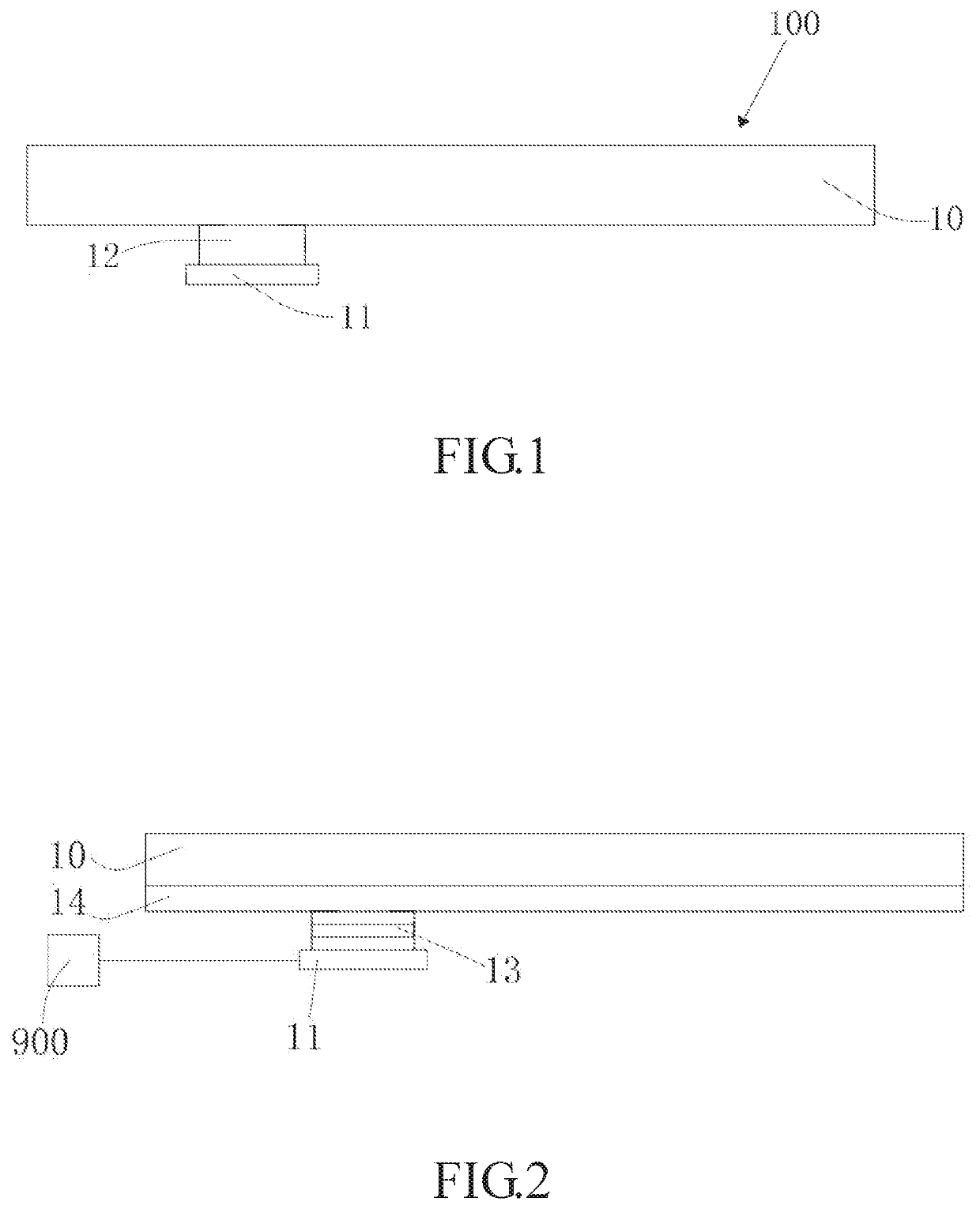
[0031]In the description of this disclosure, it is to be understood that the terms “center”, “transversal”, “up,”“down,”“left,”“right,”“vertical”, “horizontal”, “top,”“bottom,”“inside” and “outside” indicating the orientation or position relationships are the orientation or position relationships based on the drawing, are only provided for the purposes of describing this disclosure and simplifying the description, but do not indicate or imply that the directed devices or elements must have the specific orientations or be constructed and operated in the specific orientations, and thus cannot be understood as the restriction to this disclosure. In addition,...


PUM


Abstract

A display panel includes a first substrate, a second substrate, active switches, pixel electrodes, a color filter layer, a light-obstructing layer, a control chip and at least one photosensor. The second substrate is disposed opposite to the first substrate. The active switches are disposed on the second substrate, and each of them comprises an electro-conductive channel. The pixel electrodes are disposed on the second substrate and coupled to the active switches. The color filter layer is disposed on the second substrate and corresponded to the pixel electrodes. The light-obstructing layer is disposed on the first substrate and disposed in correspondence with the electro-conductive channel. The light-obstructing layer covers the electro-conductive channel and is made of an electro-conductive material. The control chip is coupled to the light-obstructing layer. The photosensor is disposed between the first substrate and the light-obstructing layer.

Description

BACKGROUND OF THE INVENTIONField of the Invention[0001]This disclosure relates to a technical field of a display, and more particularly to a display panel.Related Art[0002]The liquid crystal display has many advantages, such as the thin body, low power consumption, and no radiation, and is widely applied. Most of the liquid crystal displays available in the market are backlight-type liquid crystal displays each comprising a liquid crystal panel and a backlight module. The working principle of the liquid crystal panel is to place the liquid crystal between two parallel glass substrates, and to apply a driving voltage to the two glass substrates to control the orientation of the liquid crystal, so as to refract the light emitted from the backlight module to generate an image frame.[0003]The thin-film-transistor liquid crystal display (TFT-LCD) has the properties comprising the low power consumption, excellent frame quality and higher production yield, and has gradually become the most...

Claims


Application Information

Patent Timeline
IPC IPC(8): G02F1/1335G02F1/1333
CPCG02F1/133514G02F2001/136222G02F1/13338G02F1/133512G02F1/133G09G3/3406G02F1/13318G02F1/1336G02F1/136222
Inventor CHO, EN-TSUNG
Owner HKC CORP LTD
Why Eureka
Try Eureka