
Ultrasonic sensing apparatus

a sensing apparatus and ultrasonic technology, applied in the field of sensing apparatus, can solve the problems of waste of materials, complicated process, and diesel engine hydronitrogen emission, and achieve the effect of saving material cost and convenient removal and chang

Active Publication Date: 2020-12-17
QIAN JUN TECH LTD
View PDF0 Cites 1 Cited by
  • Summary
  • Abstract
  • Description
  • Claims
  • Application Information

AI Technical Summary

Benefits of technology

The present invention provides an ultrasonic sensing apparatus with detachable and replaceable detection devices that can be used on different positions of the shell for different sensing tasks. This prevents the entire apparatus from scrapping due to failure of a single detection device. The detection devices are integrated with the housing and board to form a module, which simplifies the connection of the detection devices to the shell. This results in a cost savings and allows for efficient maintenance and replacement of worn-out detection devices.

Problems solved by technology

When the concentration of urea in the diesel is insufficient, the diesel engine may have too much hydronitrogen emission.
However, the encapsulant is adhered to a bottom of the housing, so that entire of an ultrasonic sensing apparatus may be retired when the piezoelectric sheet is damaged.
Specifically, when two piezoelectric sheets for different purposes are encapsulated in a housing of an ultrasonic sensing apparatus, it is necessary to inject the encapsulant on each of the two piezoelectric sheets, therefore resulting in a complicated process.
Because the piezoelectric sheets cannot be replaced, entire of an ultrasonic sensing apparatus may scrap even simply only one of the piezoelectric sheets was damaged, therefore causing waste of materials.

Method used


Image

  • Ultrasonic sensing apparatus
  • Ultrasonic sensing apparatus
  • Ultrasonic sensing apparatus

Examples


Embodiment Construction

[0030]The present invention will now be described more specifically with reference to the following embodiments. It is to be noted that the following descriptions of preferred embodiments of this invention are presented herein for purpose of illustration and description only. It is not intended to be exhaustive or to be limited to the precise form disclosed.

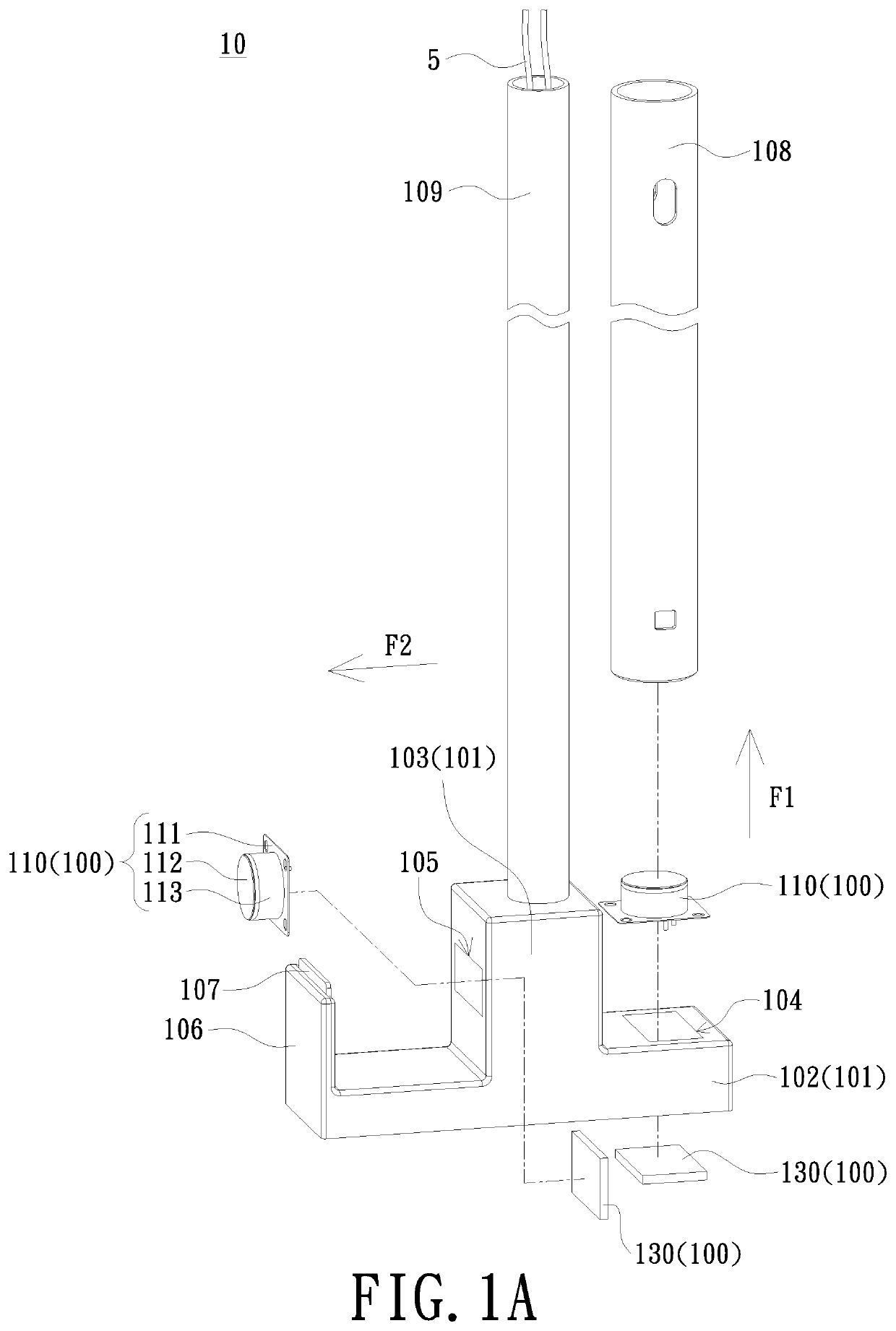
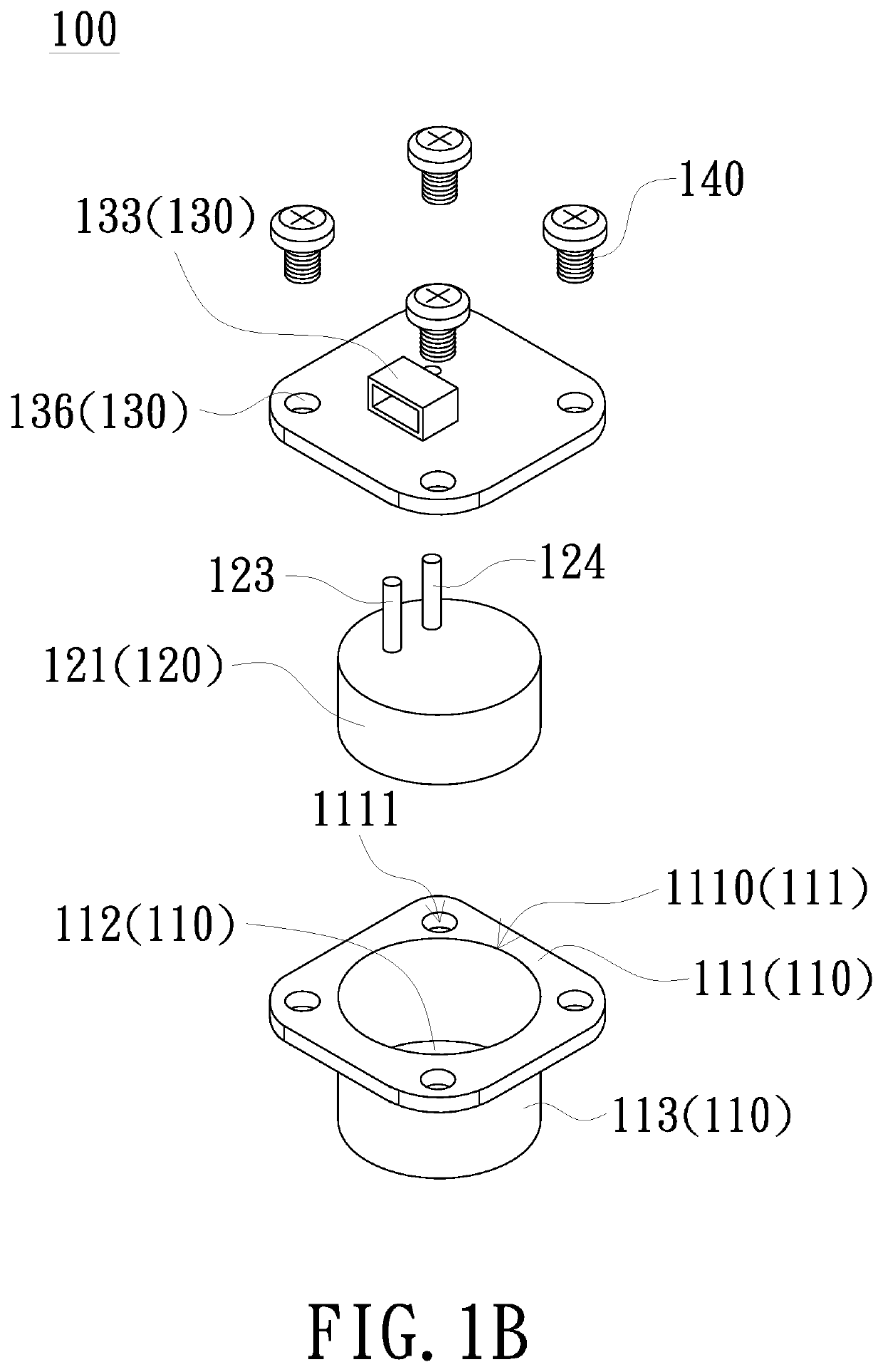
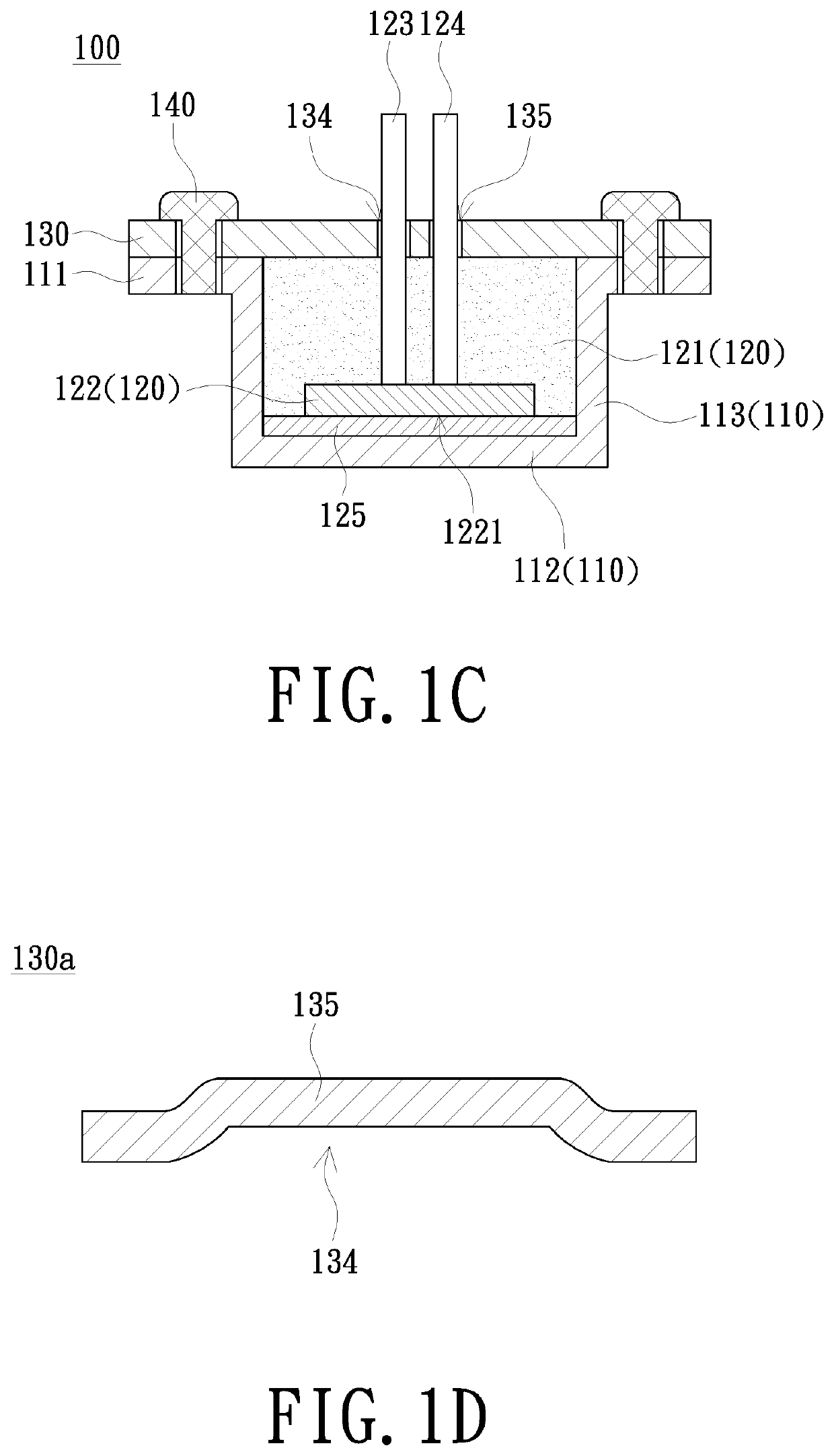
[0031]FIG. 1A is a schematic exploded view of an ultrasonic sensing apparatus of an embodiment of the present invention. FIG. 1B is a schematic exploded view of the detection device 100 in FIG. 1A. FIG. 1C is a schematic cross-sectional view of the detection device 100 in FIG. 1A. Please refer to FIGS. 1A to 1C, an ultrasonic sensing apparatus 10 of the present embodiment includes an accommodating shell 101 and at least one detection device 100.

[0032]The accommodating shell 101 includes a base 102 and a convex portion 103 connected to the base 102. A side of the base 102 has a first detection opening 104 toward a first direction ...


PUM


Abstract

An ultrasonic sensing apparatus includes an accommodating shell and at least one detection device. The accommodating shell includes a base and a convex portion connected to the base. A side of the base has a first detection opening toward a first direction, and a side of the convex portion has a second detection opening toward a second direction. Each of the at least one detection device is disposed in the base or the convex portion of the accommodating shell and includes a board, a piezoelectric assembly, a housing and a plurality of fixing members. The plurality of fixing members are configured to fix the board on the top wall of the housing to press the board to the encapsulating body of the piezoelectric assembly, thereby pressing the piezoelectric sheet to the bottom wall.

Description

FIELD OF THE INVENTION[0001]The present invention relates to a sensing apparatus, and more particularly to an ultrasonic sensing apparatus including multi-purpose.BACKGROUND OF THE INVENTION[0002]A diesel engine needs to be equipped with Selective catalytic reduction (SCR) to reduce toxic nitrogen oxide (NOx) emission. SCR can neutralize the toxic hydronitrogen by adding urea to the diesel fuel to convert the toxic hydronitrogen into water and nitrogen. When the concentration of urea in the diesel is insufficient, the diesel engine may have too much hydronitrogen emission.[0003]The urea used in the diesel engine may be mixed with water and stored in a storage tank adjacent to the diesel engine. Usually, a plurality of ultrasonic detecting devices can be arranged beside the storage tank to detect the urea concentration or liquid level of the urea in the storage tank.[0004]The conventional ultrasonic sensing apparatus primarily comprises a housing and a piezoelectric sheet placed in t...

Claims


Application Information

Patent Timeline
IPC IPC(8): G01N29/02G01N29/22G01F23/296
CPCG01N29/02G01N2291/022G01F23/296G01N29/22G01N29/2437G01N29/222G01N2291/02809G01N2291/02836G01N2291/0228G01F23/2968H10N30/88H10N30/302
Inventor FU, YU-YENYEH, PO-CHUNCHEN, DONG-FU
Owner QIAN JUN TECH LTD
Learn More