
Variable frequency drive and method of its air cooling

Active Publication Date: 2020-12-17
KHACHATUROV DMYTRO
View PDF0 Cites 1 Cited by
  • Summary
  • Abstract
  • Description
  • Claims
  • Application Information

AI Technical Summary

Benefits of technology

[0020]A technical result, achieved from implementation of the claimed invention lies in improving of maintainability, as well as increasing of ergon

Problems solved by technology

The disadvantages of the described invention include the increasing dimensions in the operating conditions and the presence of flexible connection of heat exchangers could lead to their failure and violation of the tightness of the circuit.
The disadvantages of the described technical solutions include a large number of fans, which leads increasing of dimensions of the device.
The disadvantages of the described method include the scheme of air flow moving, according to which a heated air enters t

Method used


Image

  • Variable frequency drive and method of its air cooling
  • Variable frequency drive and method of its air cooling
  • Variable frequency drive and method of its air cooling

Examples


Example

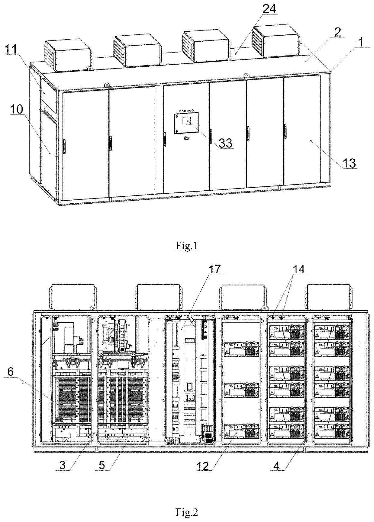
[0034]The variable frequency drive (FIG. 1), is made in a monoblock design cabinet in a form of a rectangular parallelepiped with openings for doors, sealed terminal chambers and assembly covers of cooling system elements. The cabinet enclosure 1 is divided into a length by two compartments with power and low-current electronic components and a control unit. The cabinet 1 is designed with a double-circuit forced air cooling system.

[0035]One of said compartments is sealed 2 and comprising a first air circuit (an internal cooling circuit) and local modules 3; 4 (FIG. 2) with the power and low-current electronic components.

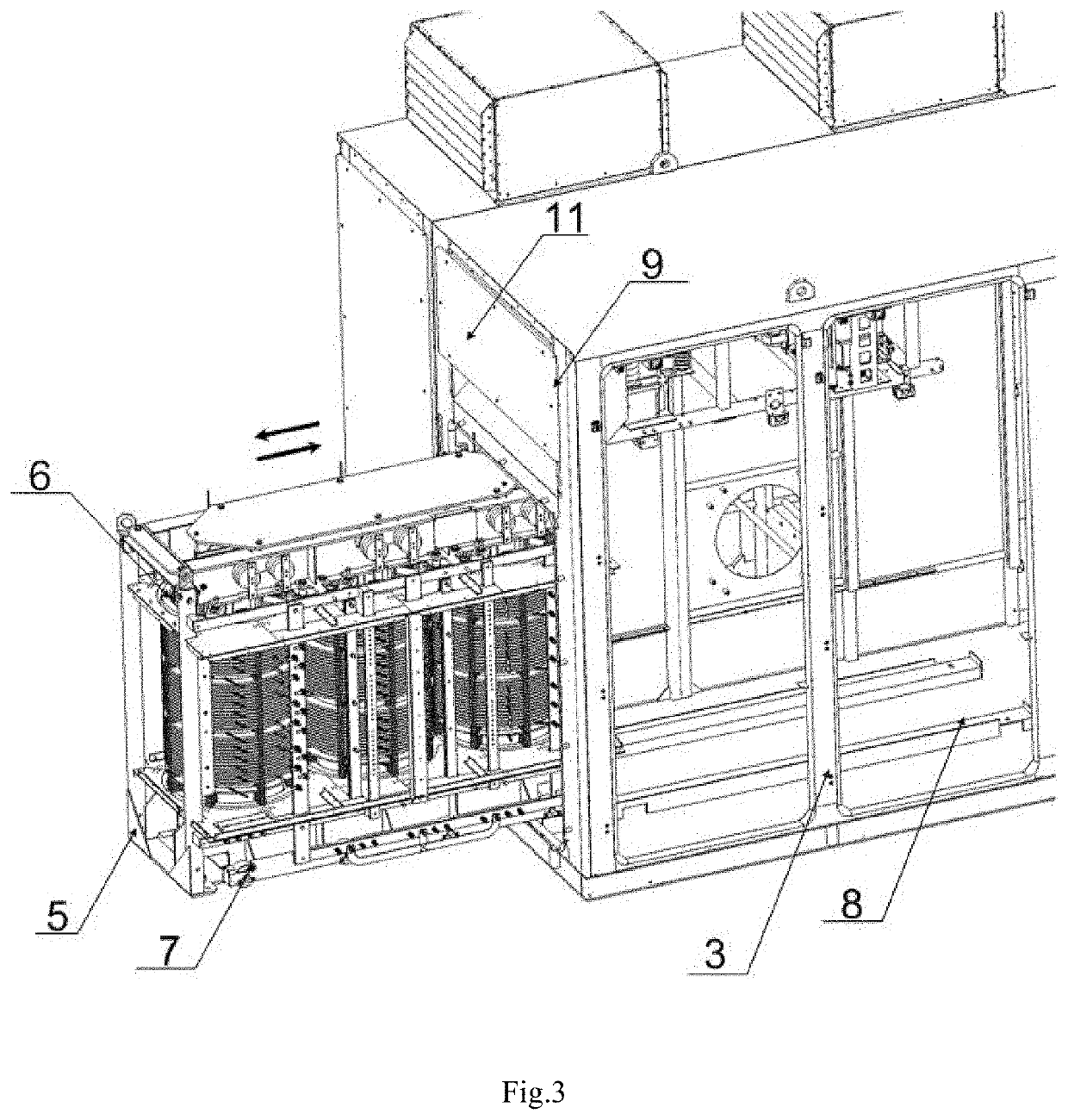
[0036]Local module 3 is designed for transformer. Wherein a transformer 6 (FIG. 3) is installed on a movable frame 5. According to present invention the transformer 6 could be designed as dry-type transformer, also it could be another well known type of transformer.

[0037]The movable frame 5 comprising a roller base 7 with a guiding ways 8. Described structure allows ...


PUM


Abstract

Variable frequency drive and method of its air cooling relates to the field of electrical engineering, in particular, to the fields of frequency drive (FD) and converter technology with a forced double-circuit air cooling system and designed for using in sealed cabinet structures. The first air circuit formed by loop air moving around each of local modules 3; 4 of the sealed compartment with using the circulation fan 26. Describes special structure of local modules 3; 4 allows to perform the cooling air barrier between the cabinet enclosure and each local module of the sealed compartment with using the internal air channel 18.

Description

CROSS-REFERENCES TO RELATED APPLICATIONS[0001]The present patent application claims priority to Ukrainian patent application a201906697 filed Jun. 14, 2019.FIELD OF THE INVENTION[0002]The claimed invention relates to the field of electrical engineering, in particular, to the fields of frequency drive (FD) and converter technology with a forced air cooling system and designed for using in medium-voltage / high-voltage frequency drives and other electrical devices cabinet structures.BACKGROUND OF THE INVENTIONDescription of the Related Art[0003]Currently known methods and systems for air cooling of high-voltage electrical equipment. Such equipment emitting significant dissipated energy in the form of heat. Prior art air cooling systems designed for removing a generated heat through both natural and forced ventilation methods.[0004]Forced air cooling systems usually made in a form of a sealed enclosure with a double-circuit cooling system, wherein the internal circuit is sealed and conne...

Claims


Application Information

Patent Timeline
IPC IPC(8): F04B39/06H05K7/20
CPCF04B39/06H05K7/20918H05K7/206F04B39/066H05K7/20145
Inventor KHACHATUROV, DMYTRO
Owner KHACHATUROV DMYTRO
Learn More