
Squat exercising machine

a technology of squats and exercise machines, applied in the field of fitness equipment, can solve the problems of increasing the chance of physical injury, poor training effect, and the volume of conventional squat training devices, and achieve the effects of convenient storage, convenient setting, and enhanced efficiency

Inactive Publication Date: 2020-11-19
GEARON MICHAEL JAMES
View PDF0 Cites 2 Cited by
  • Summary
  • Abstract
  • Description
  • Claims
  • Application Information

AI Technical Summary

Benefits of technology

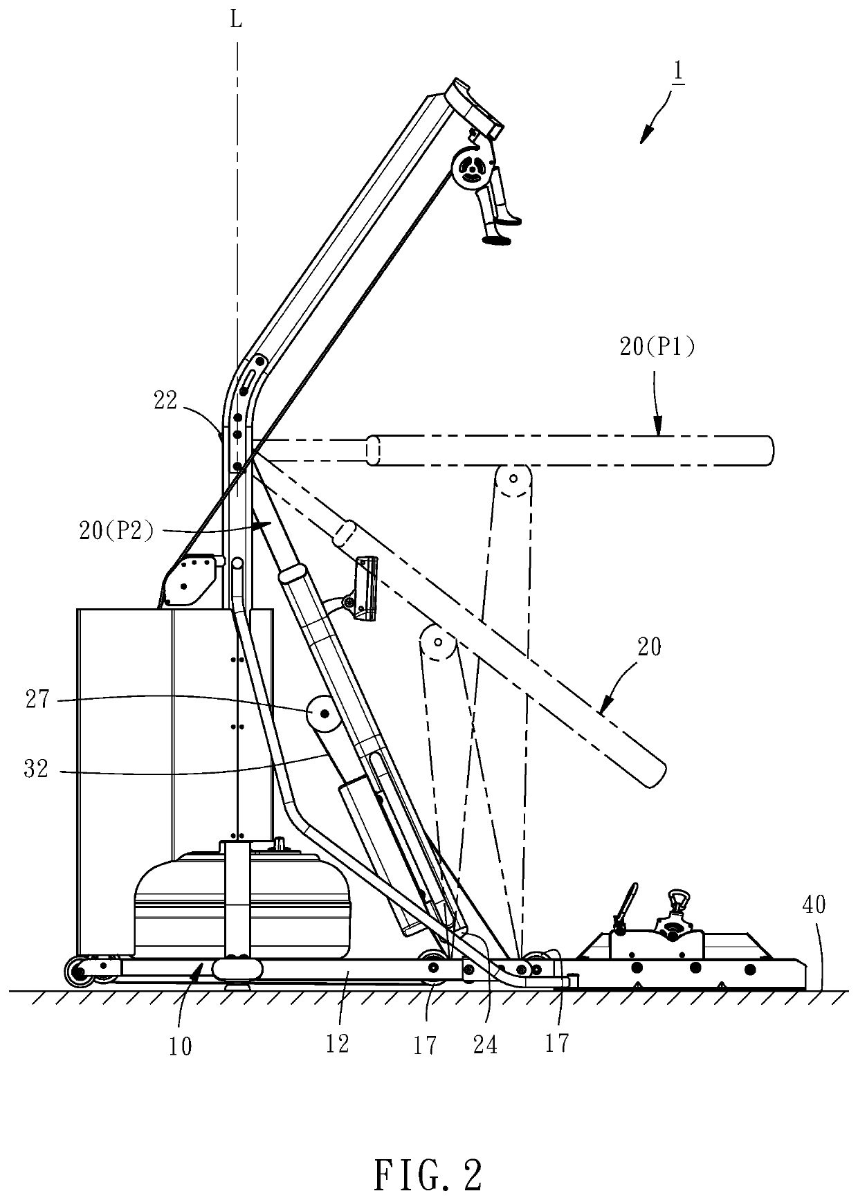
The present invention is a squat exercising machine that can be easily stored when not in use and easily transitioned to an exercise state by the user. It is made up of a base mount, a swivel rack, and a resistance device. The swivel rack can be moved from a received position to an exercising position by the user, and it has a pivot that connects to the base mount. The angle between the swivel rack and a plumb line is less than 30 degrees when the machine is in the received position. This allows for efficient use of space when the machine is not in use.

Problems solved by technology

For beginners, the aforesaid training method may be liable to train undesired muscle groups due to wrong posture, resulting in poor training effect and increase of the chance of physical injury.
However, the aforesaid mechanism makes the conventional squat training device have a considerable volume, which is not conducive to space utilization.
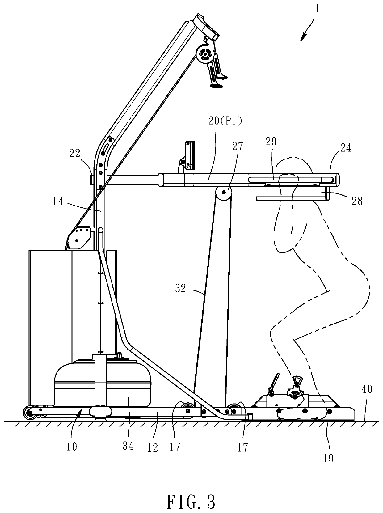
In particular, the shoulder abutment portion is usually configured protruding over a base mount of the conventional squat training device in order that the shoulder abutment portion can be properly abutted by the user's shoulders, resulting in that the user may get injury due to accident bump with the shoulder abutment portion.

Method used


Image

  • Squat exercising machine
  • Squat exercising machine
  • Squat exercising machine

Examples


Embodiment Construction

[0010]The structure and technical features of the present invention will be detailedly described hereunder by a preferred embodiment and accompany drawings.

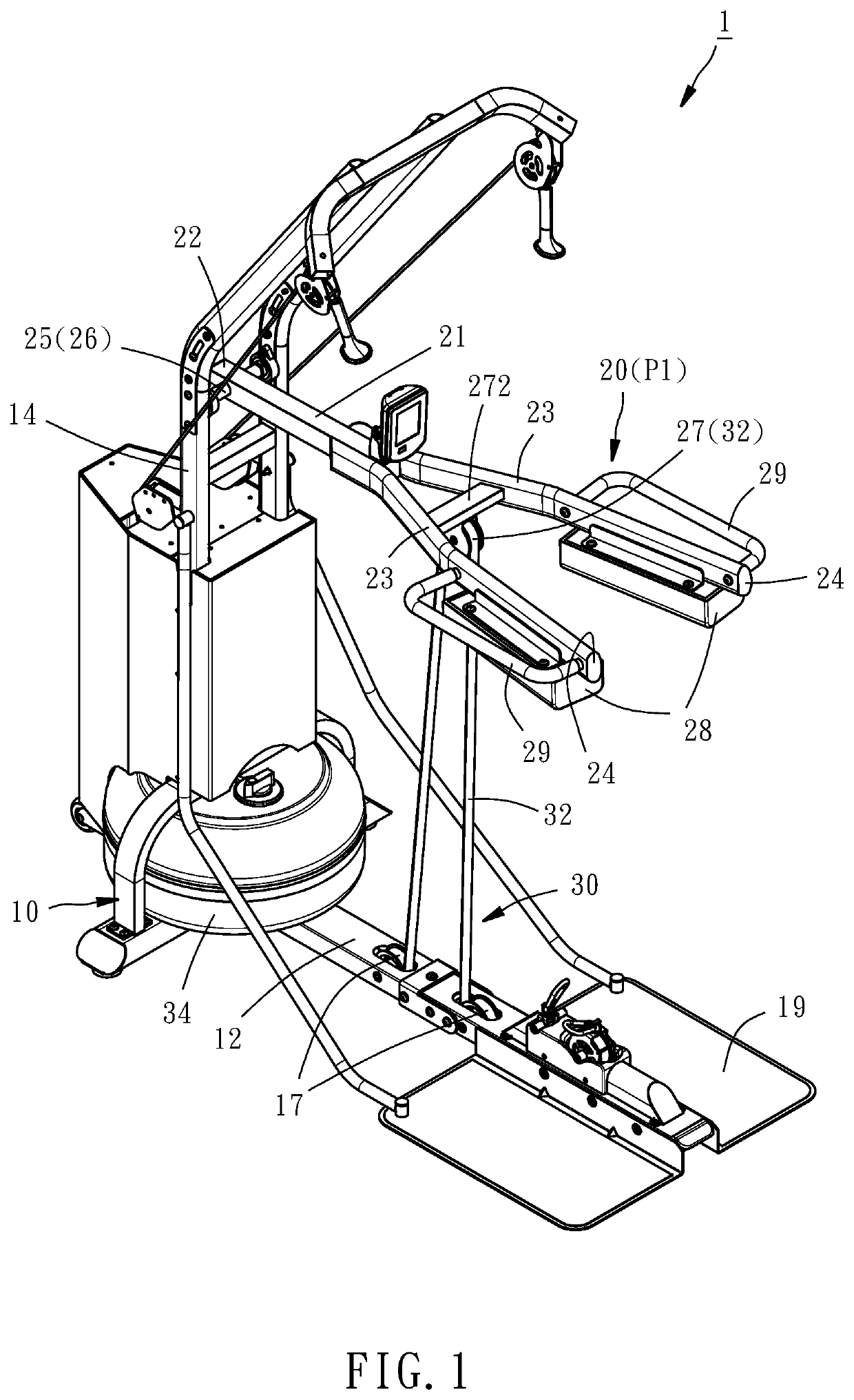
[0011]As shown in FIGS. 1-2, a squat exercising machine 1 provided by a preferred embodiment of the present invention is composed of a base mount 10, a swivel rack 20, and a resistance device 30 connected with the swivel rack 20.

[0012]The base mount 10 includes a base frame 12 to be placed on a support surface 40, a stand frame 14 extending upwardly from the base frame 12, two lower pulleys 17 disposed on the base frame 12, and two pedals 19 disposed at an end portion of the base frame 12 remote from the stand frame 14 for being stepped by a user thereon. The two pulleys 17 are located between the stand frame 14 and the pedals 19. The support surface 40 may be a floor, a ground or any surface that may support the base frame 12.

[0013]The swivel rack 20 is a Y-shaped member, including a support member 21, a first end 22 at a termin...


PUM


Abstract

A squat exercising machine (1) includes a base mount (10), a swivel rack (20) and a resistance device (30) connected with the swivel rack (20). The swivel rack (20) has a first end (22), a second end (24) opposite to the first end (24), a shoulder abutment portion (28) adjacent to the second end (24), and a pivot portion (25) adjacent to the first end (22) and pivotally connected with the base mount (10) by a pivot (26) in a way that the swivel rack (20) is upwardly swingable about the pivot (26) from a received position (P2) to an exercising position (P1). An included angle between an imaginary line that passes through the first and second ends (22, 24) and an imaginary plumb line (L) is equal to or less than 30 degrees when the swivel rack (20) is positioned at the received position (P2) and viewed from an end of the pivot (26). As such, the squat exercising machine (1) can be set in a received state for easy storage, thereby increasing space using efficiency.

Description

BACKGROUND OF THE INVENTION1. Field of the Invention[0001]The present invention relates generally to a fitness equipment and more particularly, to a squat exercising machine.2. Description of the Related Art[0002]Squat exercise is conventionally realized by using barbell as an assistant tool. For beginners, the aforesaid training method may be liable to train undesired muscle groups due to wrong posture, resulting in poor training effect and increase of the chance of physical injury. Mechanical equipment, such as a squat training device having a fixed motion trajectory, is generally used to help beginners to do squat exercise with a correct body posture so as to effectively reduce the chance of physical injury.[0003]The conventional squat training device is equipped with a shoulder abutment portion, which is able to be moved in a predetermined trajectory and adapted to be abutted by user's shoulders, such that the user can do the squat exercise by following the trajectory. The squat...

Claims


Application Information

Patent Timeline
IPC IPC(8): A63B21/00A63B23/035A63B23/12
CPCA63B21/4047A63B2023/0411A63B23/12A63B23/03525A63B21/0084A63B21/154A63B21/159A63B23/0405A63B2210/50A63B21/4034A63B21/4035
Inventor GEARON, MICHAEL JAMES
Owner GEARON MICHAEL JAMES
Learn More