
Signal transmitter device and calibration method

Active Publication Date: 2020-11-12
REALTEK SEMICON CORP
View PDF0 Cites 1 Cited by
  • Summary
  • Abstract
  • Description
  • Claims
  • Application Information

AI Technical Summary

Benefits of technology

The present patent provides a calibration method for a signal transmitter device. The method involves mixing multiple calibration signals with an oscillating signal to transmit a signal with reduced distortion. The device detects the power of the transmitted signal and generates a set of coefficients based on the detected power. Using these coefficients, the device generates new calibration signals that reduce the pulling effects of both the transmitted signal and external circuits. This results in improved performance of multiple transmitters in the device for multiple channel transmission applications.

Problems solved by technology

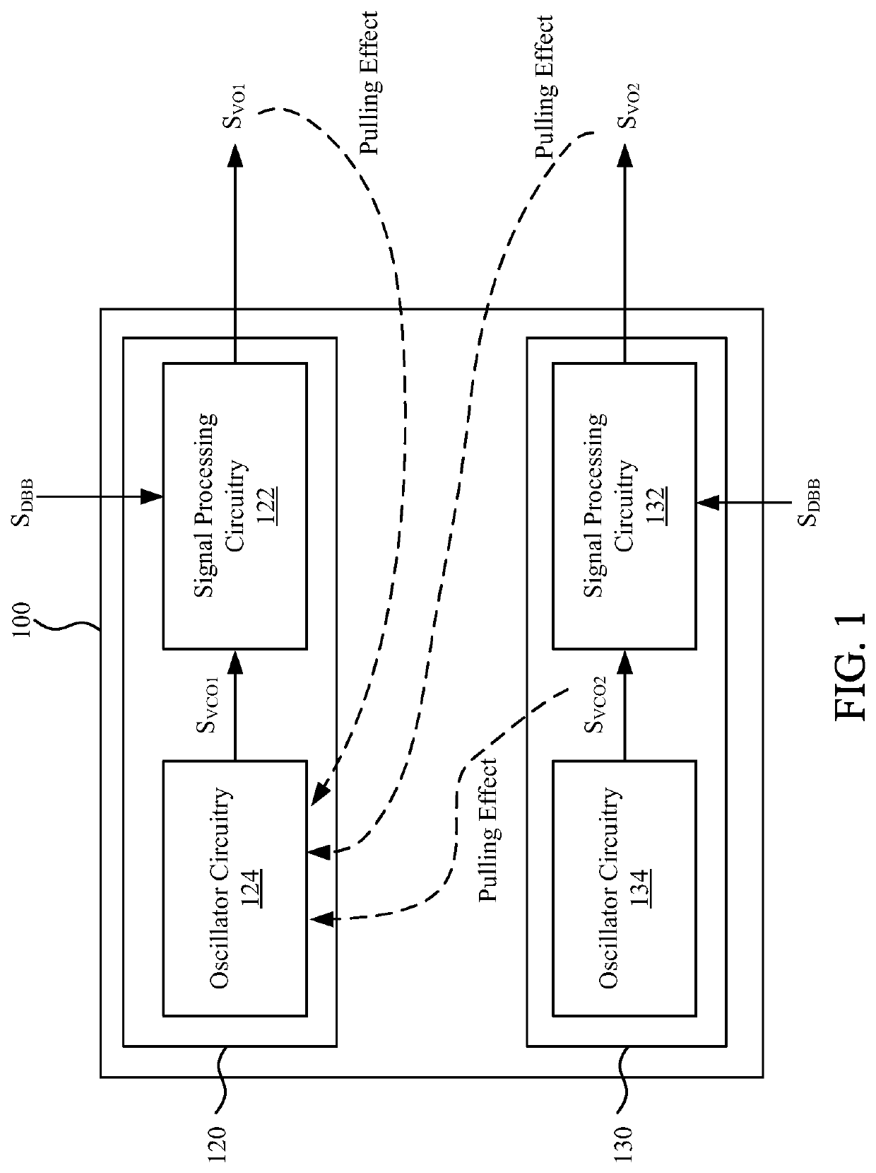
When the electronic device is equipped with multiple transmitters, multiple RF signals generated by the multiple transmitters may be coupled back to the oscillators in the respective transmitters, so that the oscillating signals generated by the oscillators have phase errors.
As such, the bandwidth required for the calibration mechanism is greater, resulting in the increase of cost and design complexity of the transmitter.
As such, unnecessary phase noise may be introduced, reducing the overall performance of the transmitter.

Method used


Image

  • Signal transmitter device and calibration method
  • Signal transmitter device and calibration method
  • Signal transmitter device and calibration method

Examples


Embodiment Construction

[0018]The embodiments are described in detail below with reference to the appended drawings to better understand the aspects of the present disclosure. However, the provided embodiments are not intended to limit the scope of the disclosure, and the description of the structural operation is not intended to limit the order in which they are performed. Any device that has been recombined by components and produces an equivalent function is within the scope covered by the disclosure. In addition, the drawings are for the purpose of illustration only and are not drawn according to the original dimensions. For ease of understanding, the same or similar elements in the following description will be denoted by the same reference numerals.

[0019]The terms “coupled” or “connected” as used herein may mean that two or more elements are directly in physical or electrical contact, or are indirectly in physical or electrical contact with each other. It can also mean that two or more elements inter...


PUM


Abstract

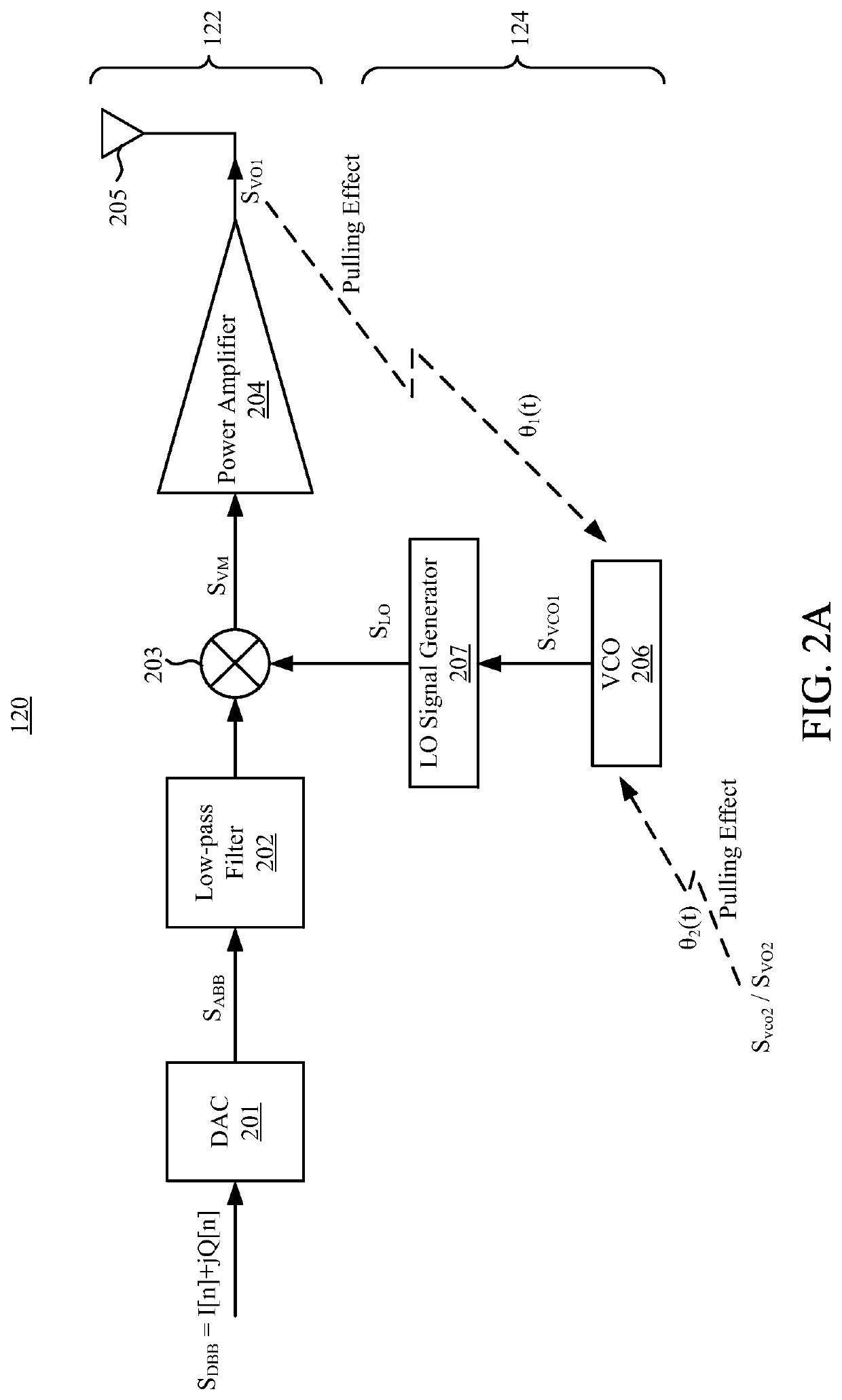
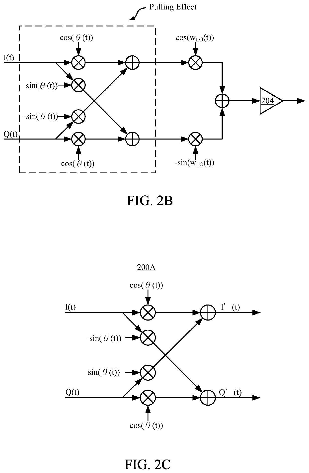
A transmitter device includes a transmitter including a first oscillator circuitry, a signal processing circuitry, and a calibration circuitry, and a second oscillator circuitry. The first oscillator circuitry is configured to output a first oscillating signal. The signal processing circuitry is configured to mix calibration signals according to the first oscillating signal, in order to emit a first output signal. The calibration circuitry is configured to detect a power of the first output signal to generate coefficients, and generate the calibration signals according to the coefficients, an in-phase data signal, and a quadrature data signal. The second oscillator circuitry is disposed adjacent to the transmitter, and is configured to output a second oscillating signal. The calibration signals are configured to reduce a pulling generated by both of the first output signal and the second oscillating signal to the first oscillator circuitry.

Description

CROSS-REFERENCE TO RELATED APPLICATION[0001]This application claims priority to Taiwan Patent Application Serial No. 108116093 filed May 9, 2019, which is incorporated herein by reference in its entirety.BACKGROUNDField of Invention[0002]The present application relates to a signal transmitter device, and particularly relates to a signal transmitter device having multiple transmitters and a calibration method for eliminating the pulling effect.Description of Related Art[0003]When the electronic device is equipped with multiple transmitters, multiple RF signals generated by the multiple transmitters may be coupled back to the oscillators in the respective transmitters, so that the oscillating signals generated by the oscillators have phase errors. The above phenomenon is generally referred to as a pulling effect.[0004]In some techniques, the pulling effect of the oscillator itself is calibrated only for a single transmitter, and the calibration mechanism is typically placed after the ...

Claims


Application Information

Patent Timeline
IPC IPC(8): H04B1/04H04L27/36H04B1/16
CPCH04B1/0475H04B1/1638H04L27/364H04B2001/0433
Inventor WANG, WEN-SHANCHANG, YUAN-SHUO
Owner REALTEK SEMICON CORP
Learn More