Small bore magnetic measurement system, method for measuring small bore magnets

a magnetic measurement system and small bore technology, applied in the field of magnetic measurement systems, can solve problems such as inability to be easily moved, and achieve the effect of eliminating interferometry equipment and being convenient to relocate and install

Active Publication Date: 2020-11-12
UCHICAGO ARGONNE LLC
View PDF0 Cites 2 Cited by
  • Summary
  • Abstract
  • Description
  • Claims
  • Application Information

AI Technical Summary

Benefits of technology

[0011]Another object of the invention is to provide a system and method for performing magnetic measurements of magnets (e.g. super-conducting undulator, SCU, magnets). A feature of the invention is that an encoder scale is moved past the read-head compared to the conventional approach of fixing the encoder scale and moving the read-head. An advantage of the invention is that it can be used to characterize small bore magnetic systems, or permanent magnet configurations, the latter of which do not rely on cryogenic temperatures.
[0012]Still another object of the invention is to provide a portable system and method for measuring magnetic fields. A feature of the invention is that it can be easily relocated and installed around an insertion device. An advantage of the invention is that it eliminates a requirement that an insertion device can only be measured in a magnetic measurement facility.
[0013]Yet another object of the present invention is to provide a compact system for characterizing fields generated by small bore magnets. A feature of the device is the use of a flexible substrate for supporting magnetic sensors and other measuring devices. An advantage of the device is the elimination of rigid, multi-meter length linear stages heretofore used to support long-length holders, for instance carbon tubes containing the sensors and other measuring devices. Another advantage is the elimination of interferometry equipment typically required to measure the position of magnetic sensors inside a magnet core.
[0014]Another object of the present invention is to provide a system and method for characterizing small bore magnets that are embedded or otherwise positioned within vacuum vessels or cryostats. A feature of the invention is that all measurement components are maintained at room temperature and atmospheric pressure, which is to say ambient temperature and pressure. An advantage of the invention is that the measurements can be made when the small bore magnet is already assembled and sequestered within an operating cryostat.
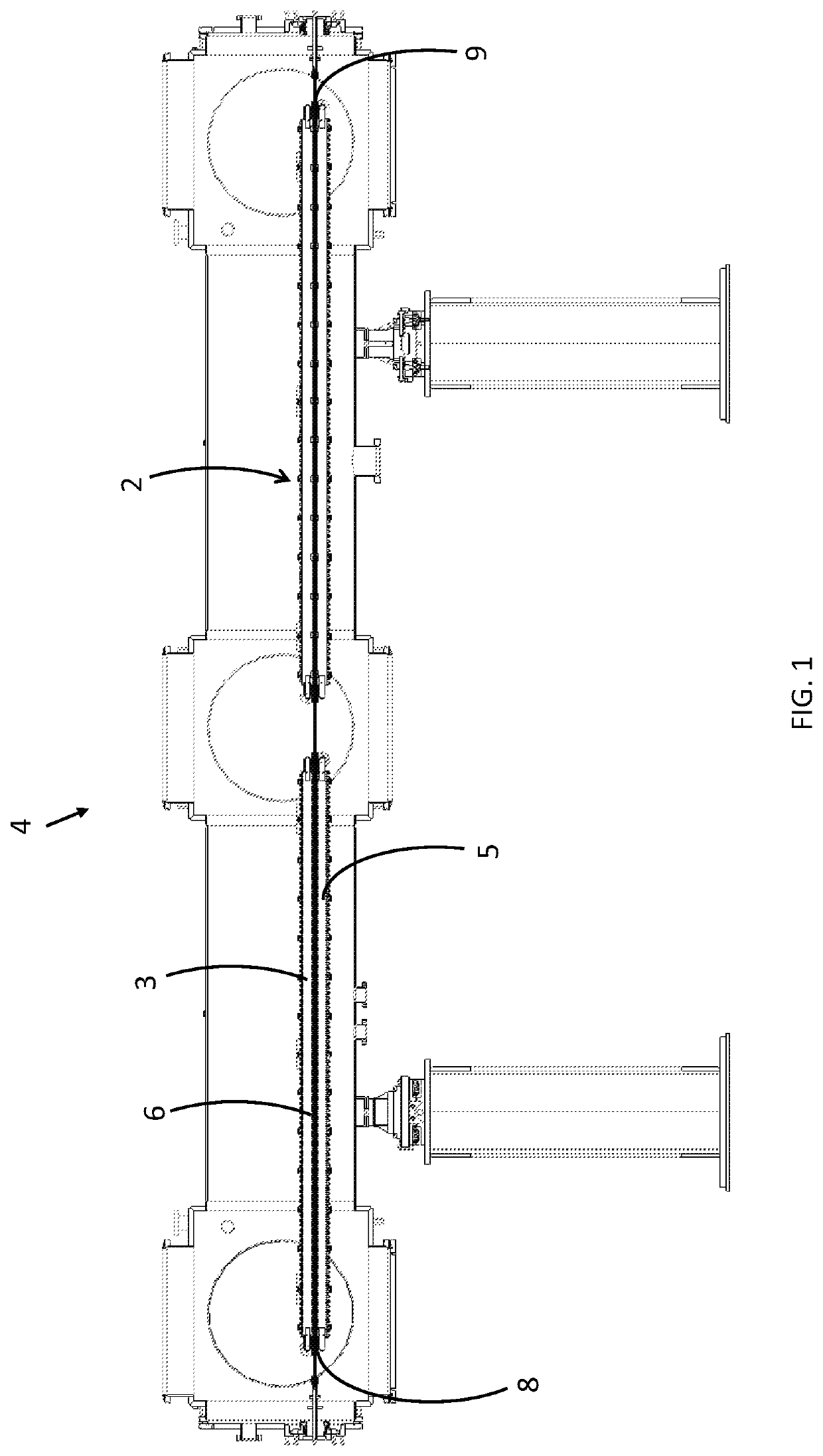
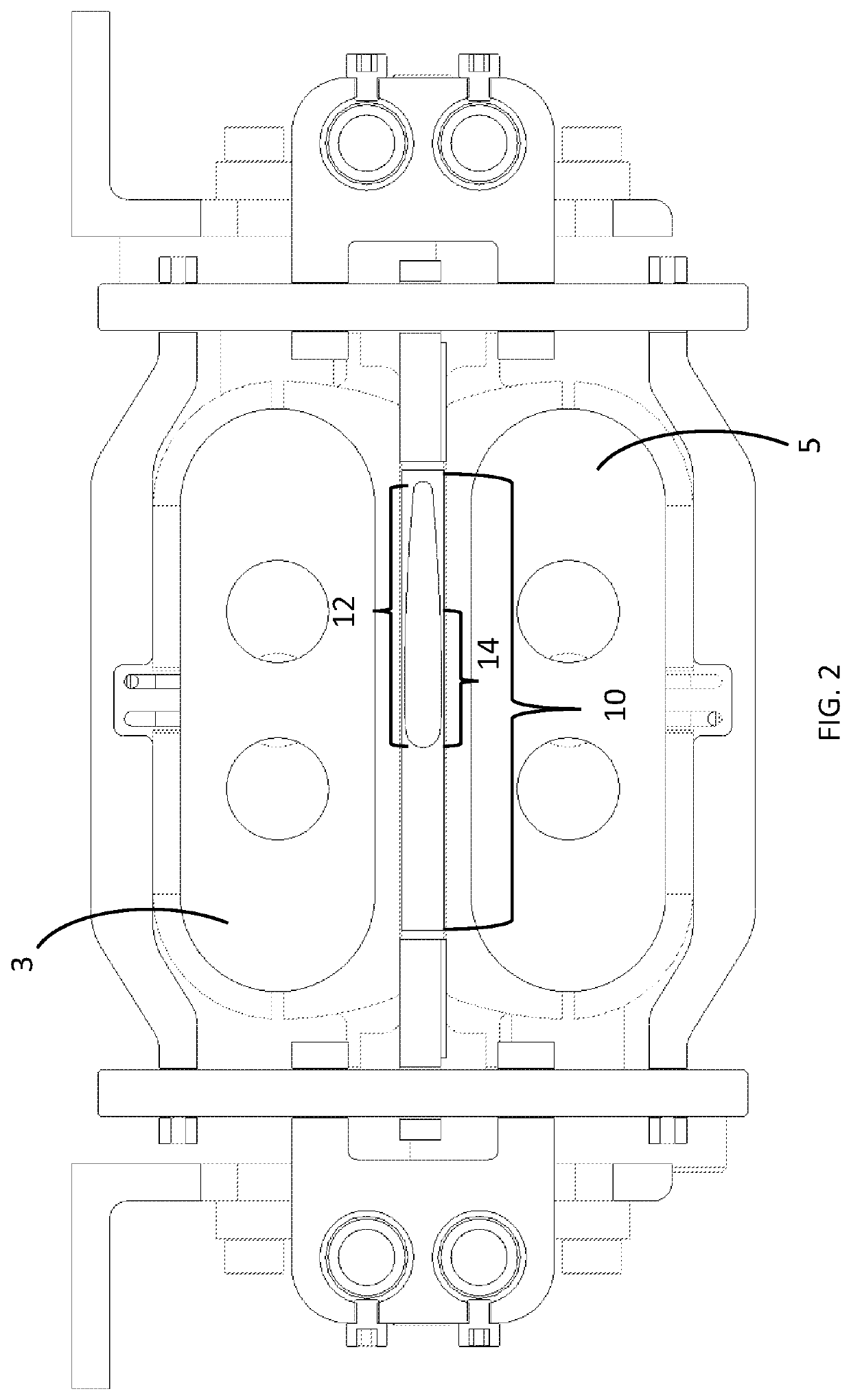
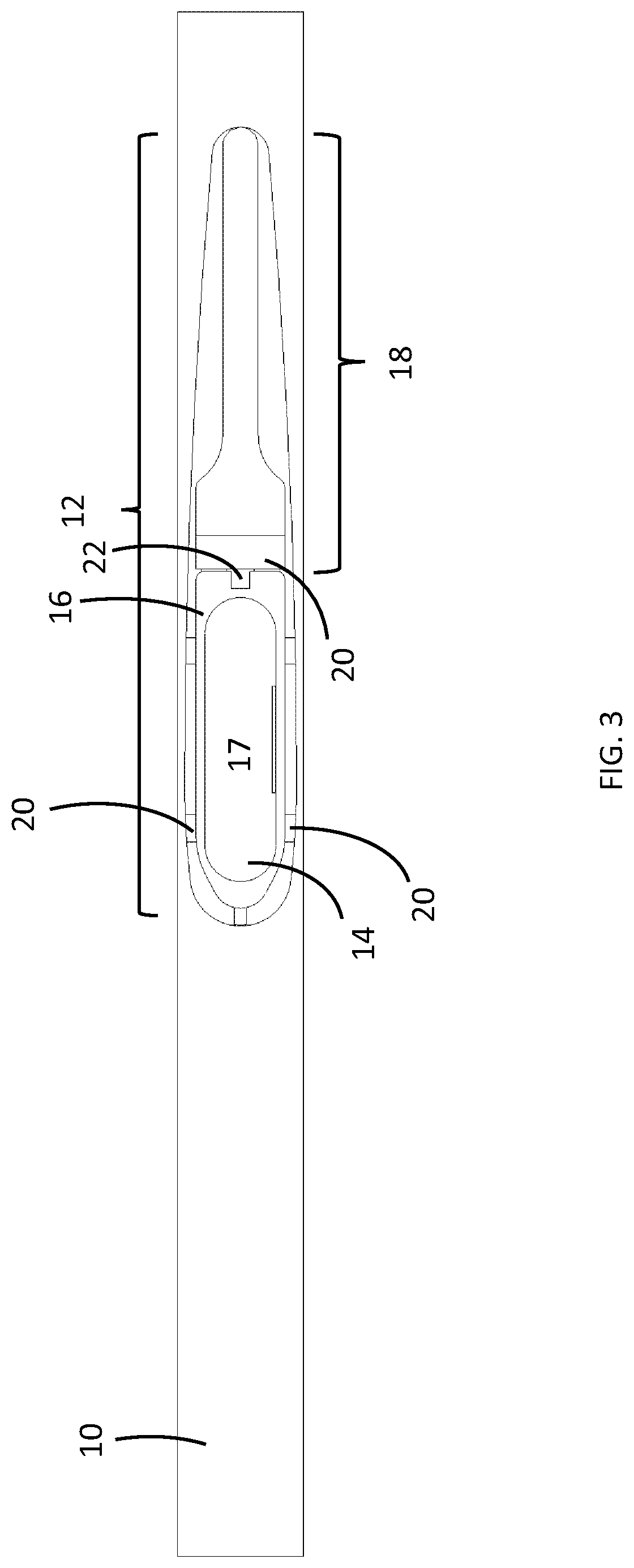
[0015]Briefly, the invention provides a system for measuring magnets, the system comprising a guide tube removably received by a beam chamber tunnel, wherein said guide tube has a first end terminating at a first end of the tunnel and a second end terminating at a second end of the tunnel; a flexible substrate removably and slidably received by the tube, wherein the flexible substrate has a first end and a second end; a first rotary stage removably attached to the first end of said flexible substrate and a second rotary stage removably attached to the second end of said flexible substrate wherein the first rotary stage and the second rotary stage effects movement of the substrate through the tube; and a Hall probe supported by the flexible substrate.
[0016]The invention also provides a method for measuring magnetic fields, the method comprising extending a measuring probe into a magnetic core while maintaining the probe at ambient temperature and pressure.

Problems solved by technology

The size and weight of such a bench makes it impossible to be easily movable, and therefore it is used stationary in a magnetic measurement facility.

Method used


Image

  • Small bore magnetic measurement system, method for measuring small bore magnets
  • Small bore magnetic measurement system, method for measuring small bore magnets
  • Small bore magnetic measurement system, method for measuring small bore magnets

Examples


Embodiment Construction

[0027]The foregoing summary, as well as the following detailed description of certain embodiments of the present invention, will be better understood when read in conjunction with the appended drawings.

[0028]All numeric values are herein assumed to be modified by the term “about”, whether or not explicitly indicated. The term “about” generally refers to a range of numbers that one of skill in the art would consider equivalent to the recited value (e.g., having the same function or result). In many instances, the terms “about” may include numbers that are rounded to the nearest significant figure.

[0029]The recitation of numerical ranges by endpoints includes all numbers within that range (e.g. 1 to 5 includes 1, 1.5, 2, 2.75, 3, 3.80, 4, and 5).

[0030]The following detailed description should be read with reference to the drawings in which similar elements in different drawings are numbered the same. The drawings, which are not necessarily to scale, depict illustrative embodiments and...


PUM


Abstract

The invention provides a system for measuring magnets, the system comprising a guide tube removably received by a beam chamber tunnel, wherein said guide tube has a first end terminating at a first end of the tunnel and a second end terminating at a second end of the tunnel; a flexible substrate removably and slidably received by the tube, wherein the flexible substrate has a first end and a second end; a first rotary stage removably attached to the first end of said flexible substrate and a second rotary stage removably attached to the second end of said flexible substrate wherein the first rotary stage and the second rotary stage effects movement of the substrate through the tube; and a Hall probe supported by the flexible substrate. Also provided is a method for measuring magnetic fields, the method comprising extending a measuring probe into a magnetic core while maintaining the probe at ambient temperature and pressure.

Description

CONTRACTUAL ORIGIN OF THE INVENTION[0001]This invention was made with government support under Contract No. DE-AC02-06CH11357 awarded by the United States Department of Energy to UChicago Argonne, LLC, operator of Argonne National Laboratory. The government has certain rights in the invention.BACKGROUND OF THE INVENTION1. Field of the Invention[0002]This invention relates to a magnetic measurement system and more specifically, this invention relates to a system and method for performing under normal operating conditions magnetic field measurements of small bore particle accelerator magnets and insertion devices for synchrotron light sources and free electron lasers.2. Background of the Invention[0003]Undulators and wigglers are used to generate intensive (e.g., coherent) beams of photons in synchrotron light sources and free electron lasers. These beams are used by scientists and engineers to perform experiments in physics, material science, biology, chemistry and other areas of sci...

Claims


Application Information

Patent Timeline
Patent Type & Authority Applications(United States)
IPC IPC(8): G01R33/07G01R33/00G01D5/14
CPCG01R33/0082G01R33/072H01L43/06G01D5/145H05H7/04H10N52/00
Inventor KASA, MATTHEW T.IVANYUSHENKOV, YURY
Owner UCHICAGO ARGONNE LLC
Why Eureka
Try Eureka