
Rapid exchange system and methods for use

Inactive Publication Date: 2020-11-12
SANFORD HEALTH
View PDF0 Cites 0 Cited by
  • Summary
  • Abstract
  • Description
  • Claims
  • Application Information

AI Technical Summary

Benefits of technology

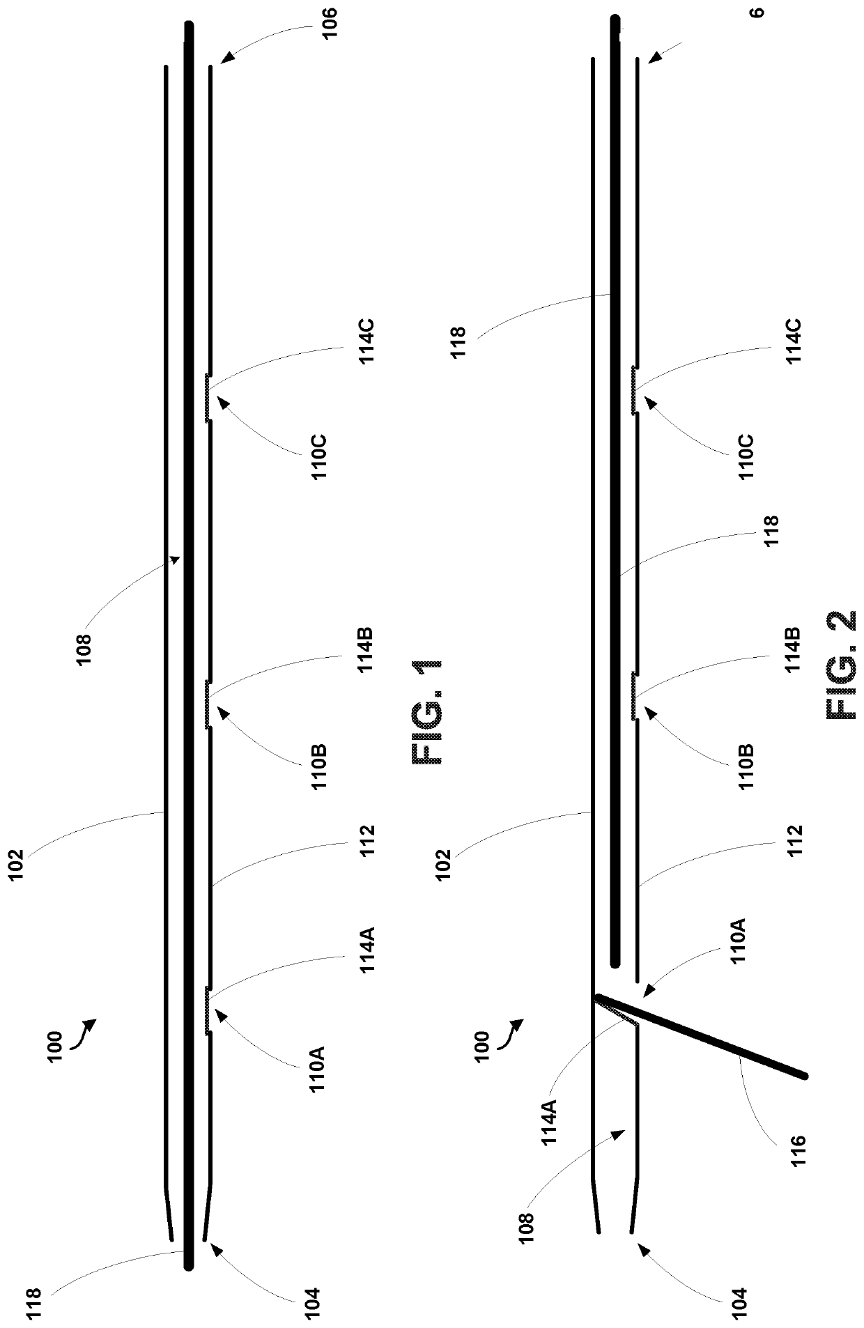
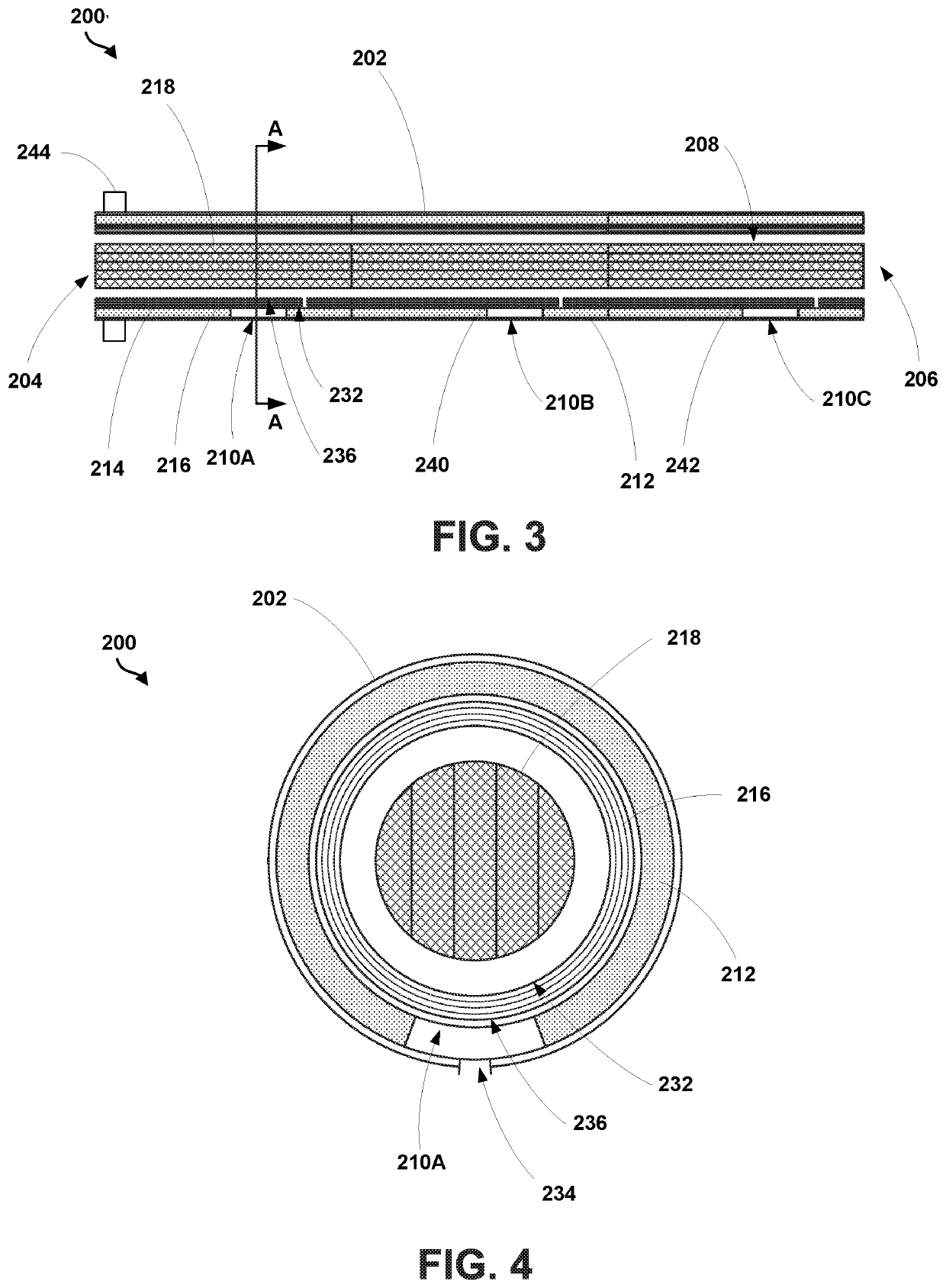
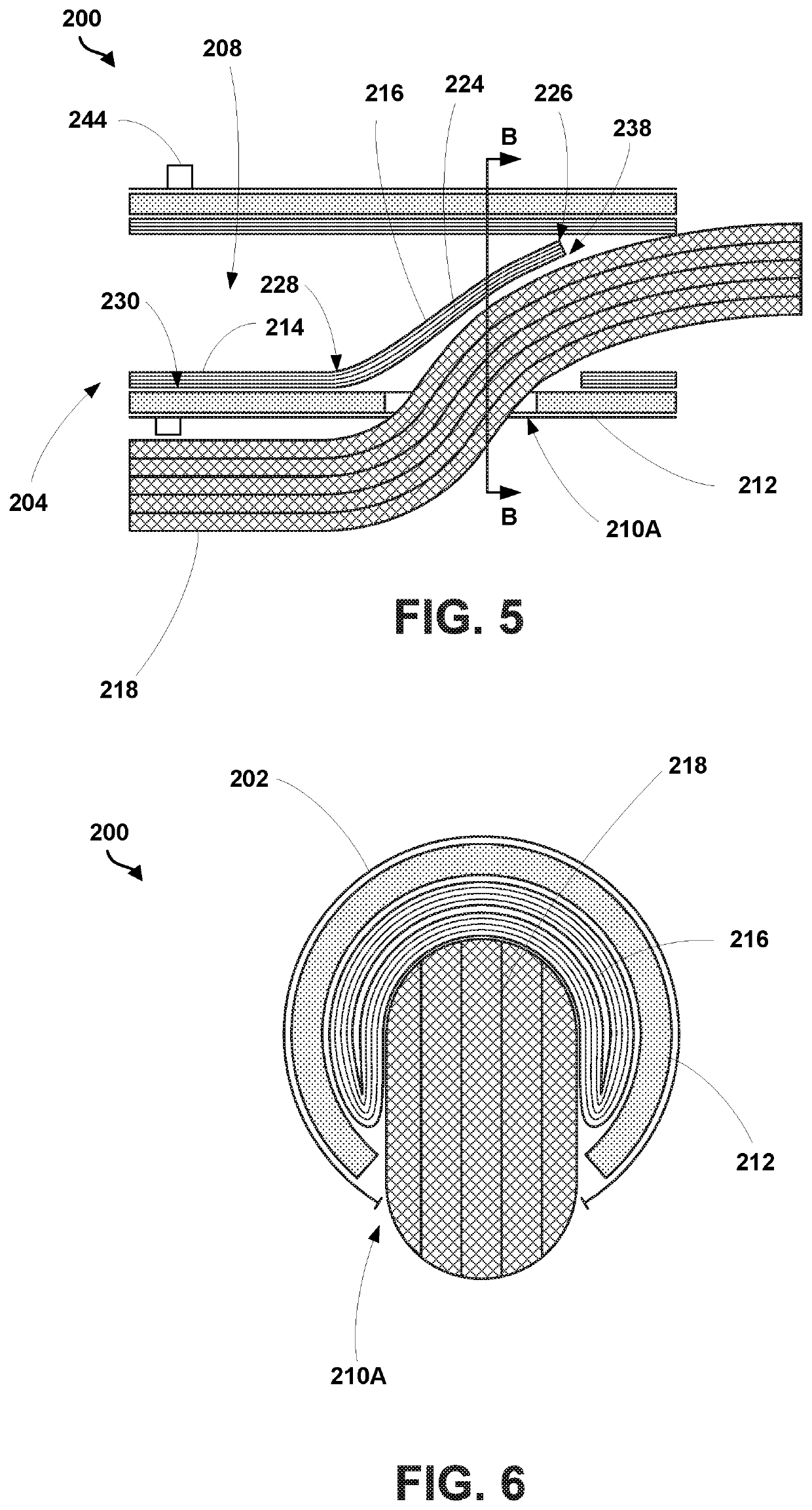
The present invention relates to a device that allows for quick disconnection when needed but can also provide full support when required. The device includes a catheter with openings in its side wall, and a covering that can be moved from a position where it partially obstructs the openings to allow for full support. The device can also include a deformable segment that can be moved to partially obstruct the openings. The invention makes it easier to access the target lumen with a guide wire, and provides flexibility in the type of support needed.

Problems solved by technology

The challenge of this solution is that the long sheaths are required to be the coaxial line for delivery of therapies.
As the length of the sheath increases, operator control and manipulation of the sheath becomes more challenging thereby adding to the complexity of cases.
Such added complexity increases procedure time and indirectly increases the likelihood of complication for the procedure.
However, rapid exchange systems have not been used as frequently in peripheral vasculature interventions for several reasons.
Yet, traditional rapid exchange systems sacrifice support for convenience.

Method used


Image

  • Rapid exchange system and methods for use
  • Rapid exchange system and methods for use
  • Rapid exchange system and methods for use

Examples


Embodiment Construction

[0018]The description of the different advantageous arrangements are presented for purposes of illustration and description, and are not intended to be exhaustive or limited to the examples in the form disclosed. Many modifications and variations will be apparent to those of ordinary skill in the art. Further, different examples may provide different advantages as compared to other advantageous examples. The example or examples selected are chosen and described in order to best explain the principles of the examples, the practical application, and to enable others of ordinary skill in the art to understand the disclosure for various examples with various modifications as are suited to the particular use contemplated.

[0019]As used herein, with respect to measurements, “about” means + / −5%.

[0020]As used herein, “substantially parallel” means + / −5%.

[0021]As used herein, “coupled” means associated directly, as well as indirectly. For example, a member A may be directly associated with a ...


PUM


Abstract

The present disclosure provides an apparatus including a catheter having a first end and a second end and defining a lumen extending from the first end to the second end. The apparatus also includes one or more openings positioned in a side wall of the catheter between the first end and the second end of the catheter. The apparatus also includes one or more coverings positioned over the one or more openings. A diverter is configured to contact a first covering of the one or more coverings to transition the first covering from a first position to a second position where the first covering projects away from a side wall of the catheter to at least partially obstruct the lumen of the catheter such that the first opening of the one or more openings is accessible via the lumen.

Description

RELATED APPLICATIONS[0001]This application claims the benefit of priority to U.S. Provisional Application No. 62 / 552,233 entitled “Rapid Exchange System and Methods for Use,” filed on Aug. 30, 2017, the contents of which are hereby incorporated by reference in its entirety.BACKGROUND THE INVENTION[0002]As the distance between the point of ex vivo arterial access and the point of in vivo treatment increases, the required catheter support needed to coaxially deliver an endovascular treatment also increases. Currently, this challenge is overcome by stiff wires and added support of long sheaths. The challenge of this solution is that the long sheaths are required to be the coaxial line for delivery of therapies. As the length of the sheath increases, operator control and manipulation of the sheath becomes more challenging thereby adding to the complexity of cases. Such added complexity increases procedure time and indirectly increases the likelihood of complication for the procedure.[00...

Claims


Application Information

Patent Timeline
IPC IPC(8): A61M25/09A61M25/00
CPCA61M2025/0079A61M2025/0183A61M25/0074A61M25/09041A61M25/10A61M2205/0266A61M25/007A61M25/005A61M25/01
Inventor KELLY, PATRICK W.
Owner SANFORD HEALTH
Learn More