
High efficiency torsion spring tacker

a torsion spring and high efficiency technology, applied in the field of torsion spring tackers, can solve the problems of unwieldy latches, prone to jamming of rear loading designs, and inconvenient assembly of latches, and achieves low friction working elements, low operating effort, and simple assembly.

Active Publication Date: 2020-11-05
WORKTOOLS
View PDF0 Cites 2 Cited by
  • Summary
  • Abstract
  • Description
  • Claims
  • Application Information

AI Technical Summary

Benefits of technology

This patent is about a tool that uses a spring to make it easier and more effortless to fasten things up. The tool has two parts: a spring and a mechanism that separates the spring when the tool is pressed. The tool can be fitted to different types of tackers and is simple and powerful to use.

Problems solved by technology

It is common that the release for one or both are imprecise and a source of force-adding friction.
Rear loading designs are prone to jamming since the staples cannot be easily accessed near the track front where jams may occur.
Such latches can be unwieldy and require aesthetic compromise.

Method used


Image

  • High efficiency torsion spring tacker
  • High efficiency torsion spring tacker
  • High efficiency torsion spring tacker

Examples


second embodiment

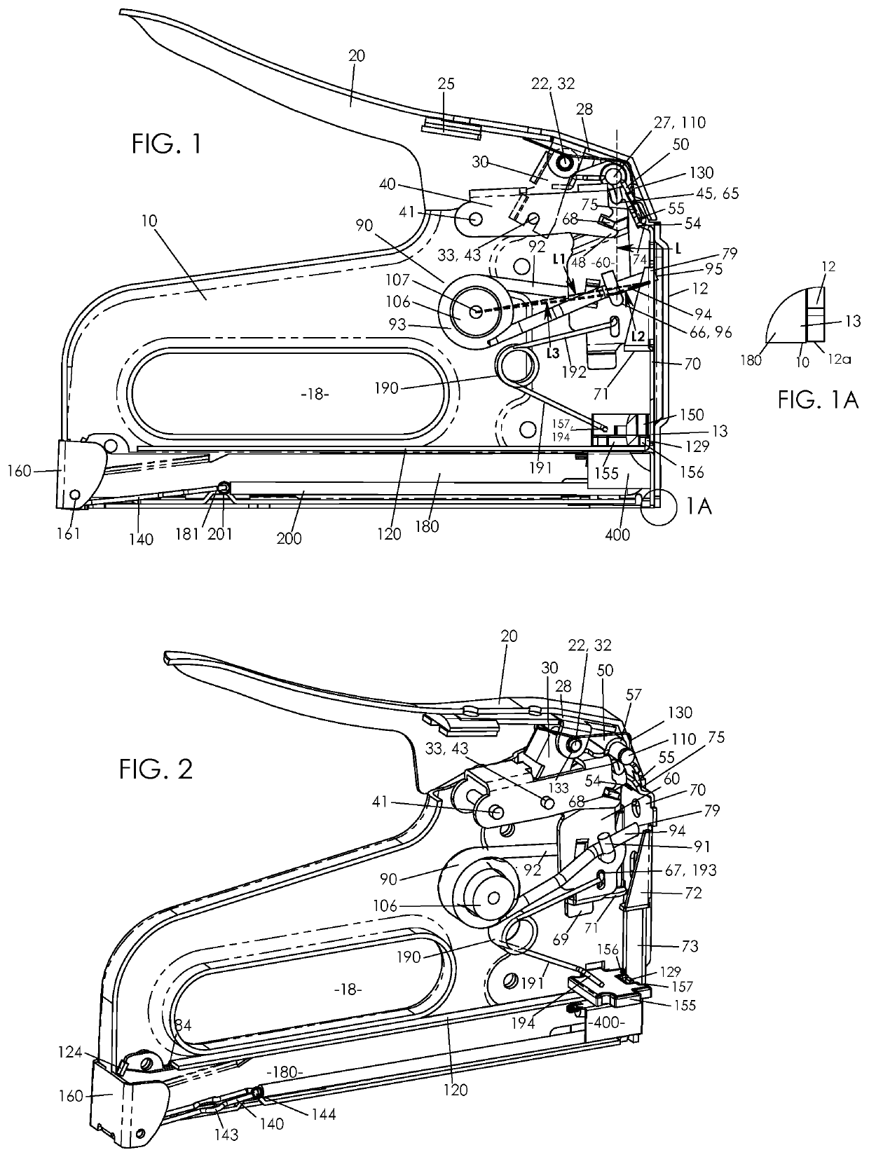
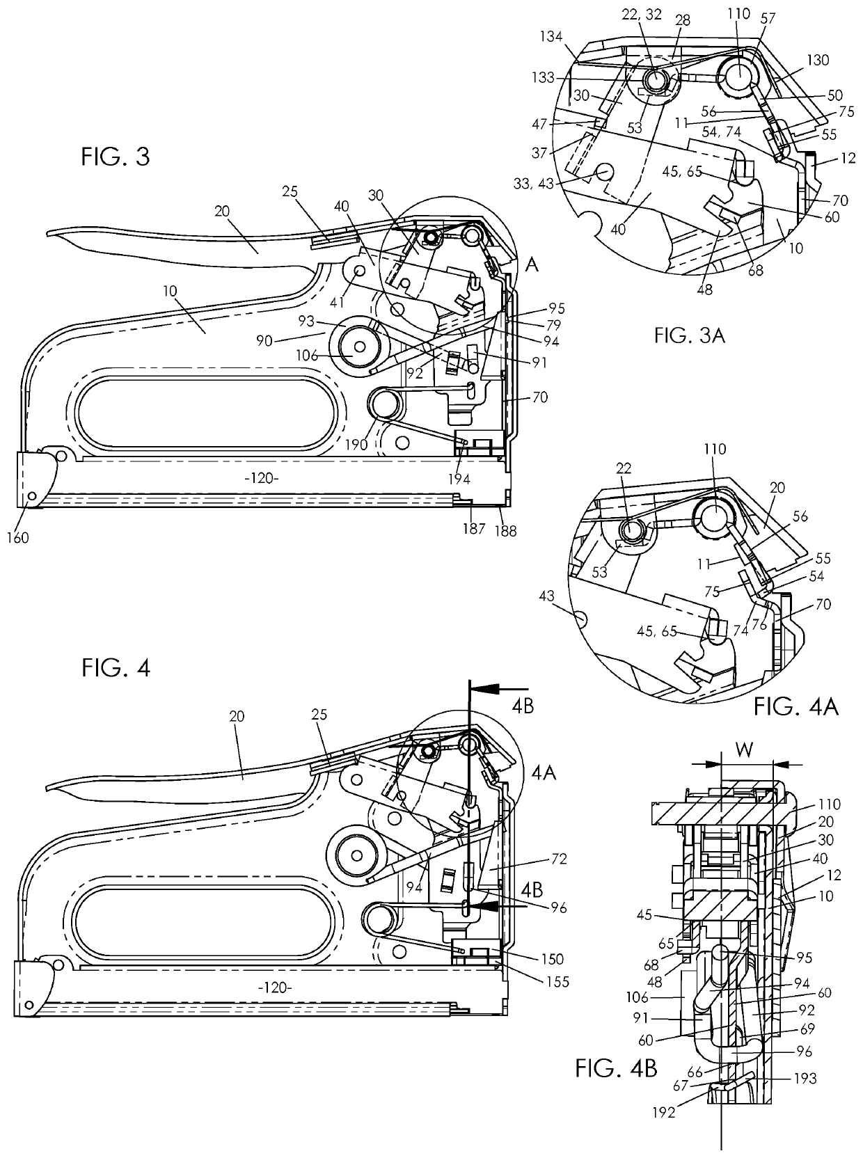
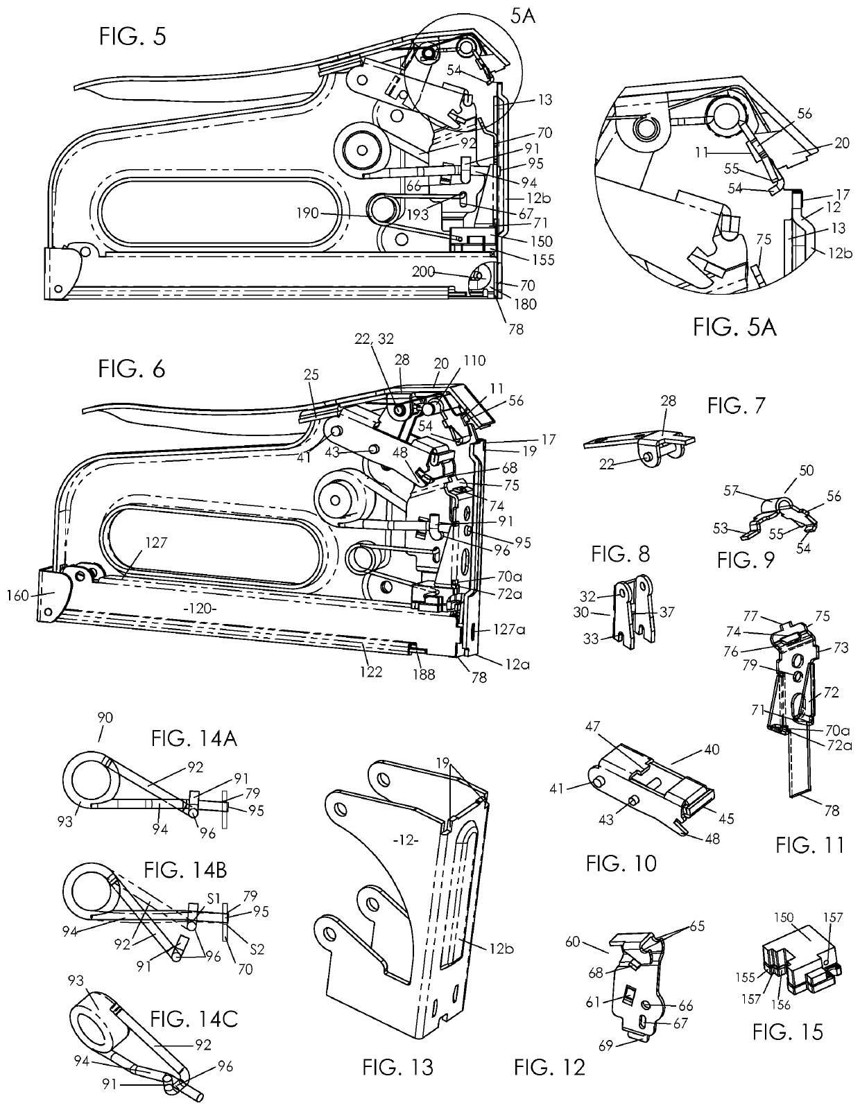
[0091]FIGS. 16 to 23 further enjoys simplified assembly. In FIGS. 19 and 23, link 330 is installed at hem 332 or equivalent structure into slots 329 of handle link support 328 while the parts are loose as depicted in FIGS. 20 and 21. Link support 328 is then fastened to handle 20 by riveting or the like, as in FIG. 16. Link 330 is thereby pivotally confined on handle 20. Hem or top end 332 presses and pivots against an underside of the handle as in FIG. 17. This pivoting is minimal, about 4 degrees as shown, so friction is low and slot 329 can be narrow. With the upper and lower respective assemblies prepared, seen in FIG. 18, the handle assembly is lowered into position as shown. Link 330 is held about at the angle shown to align with the front wall of notch 344. Link 330 is held out of the page in FIG. 18, and / or lever 340 pressed in, so that the link may pass beside lever 340 to assume the position of FIG. 19. In both FIGS. 18 and 19, handle 20 to body pivot 27 is forward of its ...

first embodiment

[0092]Spring arm tip 95 is preferably on center with respect to a front view to press striker 70 at its center line, although an off-center alignment can also be functional. Lever 340 therefore presses spring element 96 off center at pivot 366 in a similar position as link bar 60; see FIG. 4B for this analogous position at 66 in the Lever 340 is therefore preferably off center, into the page in FIG. 16, at its three operative pivots 341, 343, and 366 to form a stable plane of action. Segment 349 may be on center, out of the page in FIG. 18, to keep its optionally exposed portion at a clean joint line of housing 10.

[0093]In FIG. 16, latch 50a operates similarly to latch 50 as disclosed with the first embodiment. Rear end 53a selectively contacts handle 20 to cause the release action. In FIG. 19, link tab 322 supports latch bias spring 130 at coil 133.

[0094]FIGS. 24 to 34 show an exemplary embodiment staple guide track and loading system preferably used with the first and second embo...


PUM


Abstract

A spring energized fastening tool with compact, rigid, low friction working elements is disclosed. A torsion power spring includes forward extending arms with the arms pressing each other proximate a front distal end of the spring. A cantilevered lever links to a handle and engages the spring adjacent to the striker. A bottom loading staple track unlatches and opens through a simple pulling-out action. Structures are provided to enable fitment with a formed sheet metal handle and housing. The fastening tool is particularly simple to assemble, powerful, and of low operating effort.

Description

CROSS-REFERENCE TO RELATED APPLICATIONS[0001]This application claims priority from provisional application No. 62 / 895,475, filed Sep. 3, 2019, and from provisional application No. 62 / 843,553, filed May 5, 2019, the contents of which are hereby incorporated by reference.FIELD OF THE INVENTION[0002]The present invention relates to spring energized tackers. More precisely, the present invention relates to a tacker with improved efficiency of assembly and operation.BACKGROUND[0003]Staple gun tackers and the like with energy storage via a power spring are known. A spring is deflected to store energy for sudden release to impact and drive a fastener into a work piece. Most commonly associated with manually operated hand tools such as a staple gun, a power spring based driving tool may also operate with a motorized system. A power spring may include a compression type, elongated bar, or torsion wire spring. With manual staple guns, a tool housing may include formed sheet metal, die cast, o...

Claims


Application Information

Patent Timeline
Patent Type & Authority Applications(United States)
IPC IPC(8): B25C5/11
CPCB25C5/11
Inventor MARKS, JOEL S.
Owner WORKTOOLS
Learn More