Fluid heating device

a heating device and fluid technology, applied in water heaters, ohmic-resistance heating details, immersion heating arrangements, etc., can solve the problems of increasing cost, affecting the heating effect of fluid, and consuming a lot of energy, so as to reduce the power supply time, uniform temperature, and reduce the effect of heating tim

Inactive Publication Date: 2020-10-29
KANG BYUNGHO
View PDF0 Cites 0 Cited by
  • Summary
  • Abstract
  • Description
  • Claims
  • Application Information

AI Technical Summary

Benefits of technology

[0015]According to the present invention described above, by inducing the circulating flow of the fluid in the vertical direction to uniformly heat the fluid, it is possible to supply the fluid having a uniform temperature.
[0016]In addition, the heating time of the fluid is significantly shortened by the generated circulating flow, so that the power supply time is greatly reduced, thereby greatly reducing the power consumption.

Problems solved by technology

In recent years, as the environmental problem has emerged seriously, the type of heating the fluid with heat generated by burning fuel is rarely used because a large amount of pollutants are discharged during the combustion process of fuel.
However, according to the conventional fluid heating device, it takes relatively long time to uniformly heat the fluid in the storage tank 100 because only the fluid located in the area adjacent to the heating unit 200, that is, the fluid in the vicinity of the heating unit 200 is heated.
Accordingly, as the power consumption is excessive, the cost increases significantly.
In addition, since the heating unit 200 is required to be separately installed at one side of the storage tank 100, the installation work is cumbersome.

Method used


Image

  • Fluid heating device
  • Fluid heating device
  • Fluid heating device

Examples


Embodiment Construction

[0024]Hereinafter, exemplary embodiments of the present disclosure will be described in detail with reference to the accompanying drawings. Throughout the specification, it is noted that the same or like reference numerals denote the same or like components even though they are provided in different drawings. Further, in the following description of the present disclosure, a detailed description of known functions and configurations incorporated herein will be omitted when it may make the subject matter of the present disclosure rather unclear.

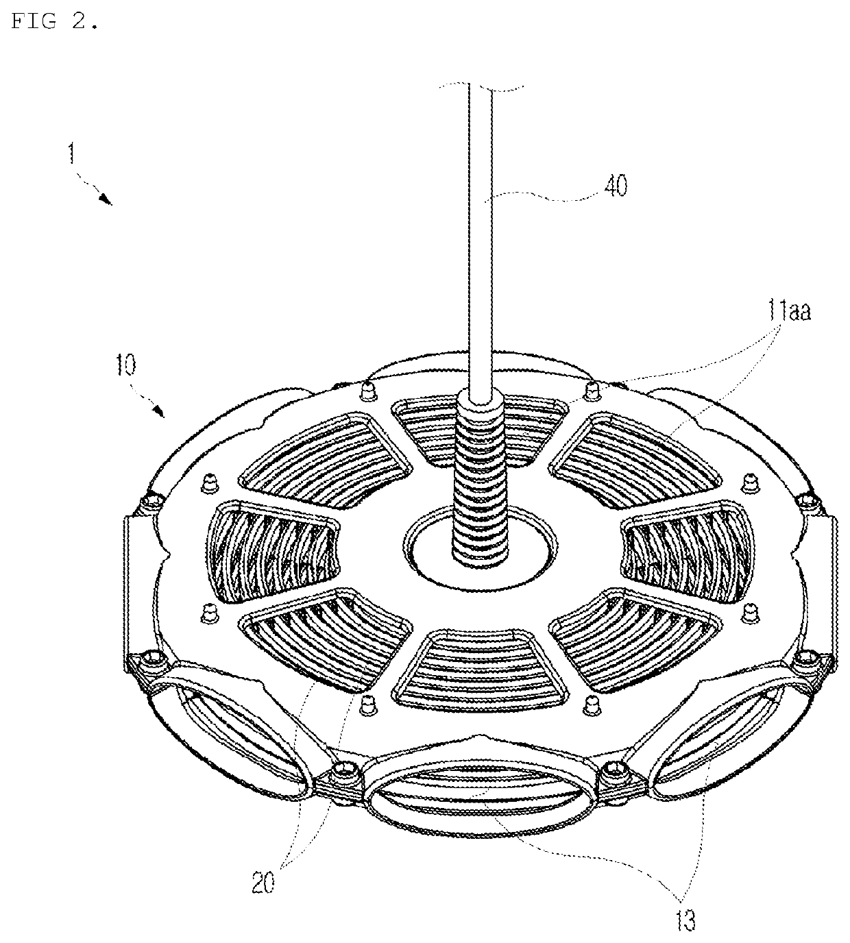
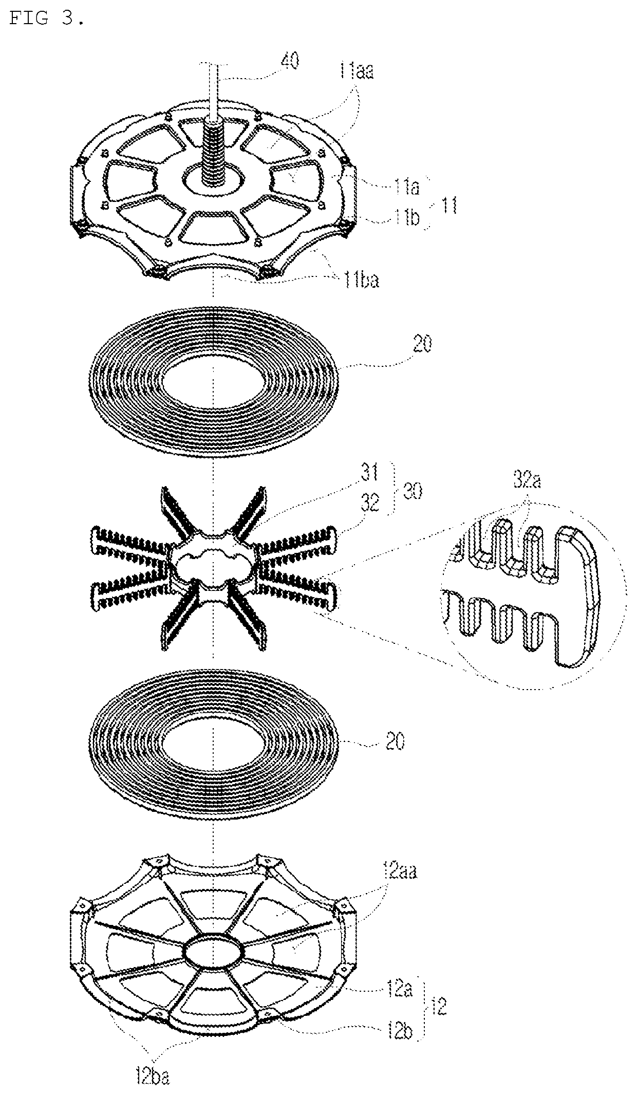
[0025]FIG. 2 is a perspective view of a fluid heating device according to an embodiment of the present invention. FIG. 3 is an exploded perspective view of a fluid heating device according to an embodiment of the present invention. FIG. 4 is a cross-sectional perspective view of a heating unit according to an embodiment of the present invention.

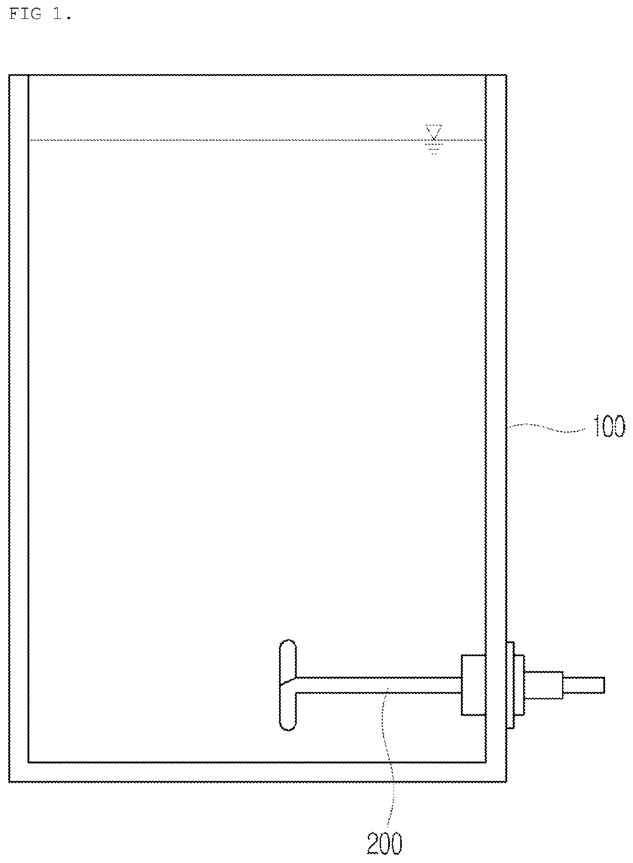
[0026]Referring to FIGS. 2 to 4, a fluid heating device 1 according to an embodiment of the present ...


PUM


Abstract

The present invention relates to a fluid heating apparatus, comprising: a housing having an upper outlet formed on the upper surface thereof, a lower outlet formed on the lower surface thereof, and at least one inlet formed on one side thereof; and a heating unit installed inside the housing and generating heat by receiving power from the outside. According to the present invention as described above, since a time for heating a fluid is remarkably shortened, the fluid can be heated more quickly to a desired temperature, and thus, power consumption can be significantly reduced.

Description

TECHNICAL FIELD[0001]The present invention relates to a fluid heating device, and more specifically, to a fluid heating device which can induce a circulating flow of a fluid in a vertical direction not only to uniformly heat the fluid, but also to significantly shorten the heating time of the fluid by the generated circulating flow.BACKGROUND ART[0002]In general, a fluid heating device is classified into a type of heating a fluid with heat generated by burning fuel and a type of heating a fluid with heat generated by electric energy.[0003]In recent years, as the environmental problem has emerged seriously, the type of heating the fluid with heat generated by burning fuel is rarely used because a large amount of pollutants are discharged during the combustion process of fuel.[0004]A fluid heating device using electric energy, which can be used wherever electricity is supplied and does not emit pollutants because there is no process of burning fuel, has been recommended.[0005]Meanwhil...

Claims


Application Information

Patent Timeline
Patent Type & Authority Applications(United States)
IPC IPC(8): F24H1/20F24H9/18H05B3/18
CPCF24H9/18H05B3/18F24H1/202F24H1/20F24H9/00H05B3/06H05B3/56H05B3/82F24H9/001F24H9/1818F24H2250/02
Inventor KANG, BYUNGHO
Owner KANG BYUNGHO
Why Eureka
Try Eureka