
Electronic percussion instrument

a technology of percussion instruments and strokes, applied in the field of electronic percussion instruments, can solve the problems of increasing the cost of products, not being able to find the position of percussion strokes with high accuracy, and contributing to the increase of the cost of products

Active Publication Date: 2020-10-15
SHEMESH GUY
View PDF21 Cites 2 Cited by
  • Summary
  • Abstract
  • Description
  • Claims
  • Application Information

AI Technical Summary

Benefits of technology

This patent describes an electronic percussion instrument that includes a body with a top opening and an internal support area, a drumhead that is stretched over the top opening, and a peripheral carrier that is supported inside the body and in contact with the drumhead bottom surface. The instrument also has at least one peripheral sensor that is placed on the internal support area and is connected to the peripheral carrier to convert vibrations into an electronic signal. Additionally, the instrument has at least one flexible circuit board that is placed within the internal support area and is connected to the at least one peripheral sensor. This flexible circuit board helps to reduce the number of electrical wire connections, which saves time and money during production. Overall, the invention provides an improved electronic percussion instrument that is easy to produce and use.

Problems solved by technology

However, these inventions do not handle finding the position of percussion strokes with high accuracy.
Furthermore, these inventions require a separate drum shell with additional interior parts, contributing to the increased cost of the product.
However, the inventions require a drum shell which adds to the cost of the product.
Furthermore the assembly contains multiple parts and the electrical connection of the plurality of sensors is labor intensive, further increasing the cost of manufacturing the product.

Method used


Image

  • Electronic percussion instrument
  • Electronic percussion instrument
  • Electronic percussion instrument

Examples


Embodiment Construction

[0029]Illustrative embodiments of the invention which are meant to be descriptive and not limiting are described with reference to the accompanying figures.

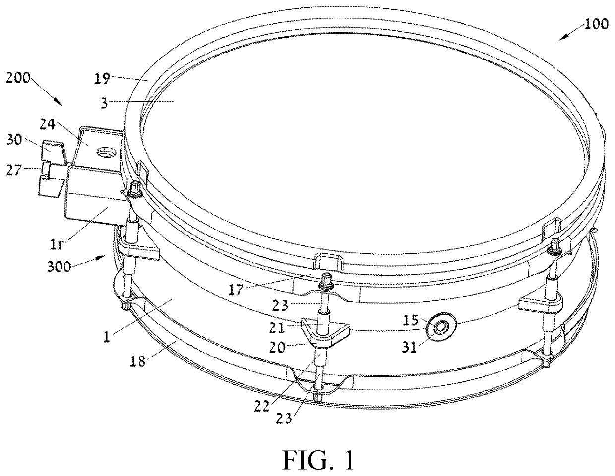
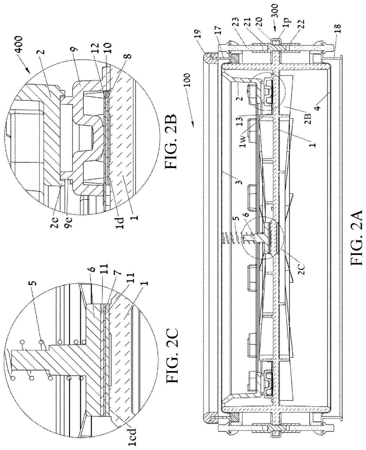
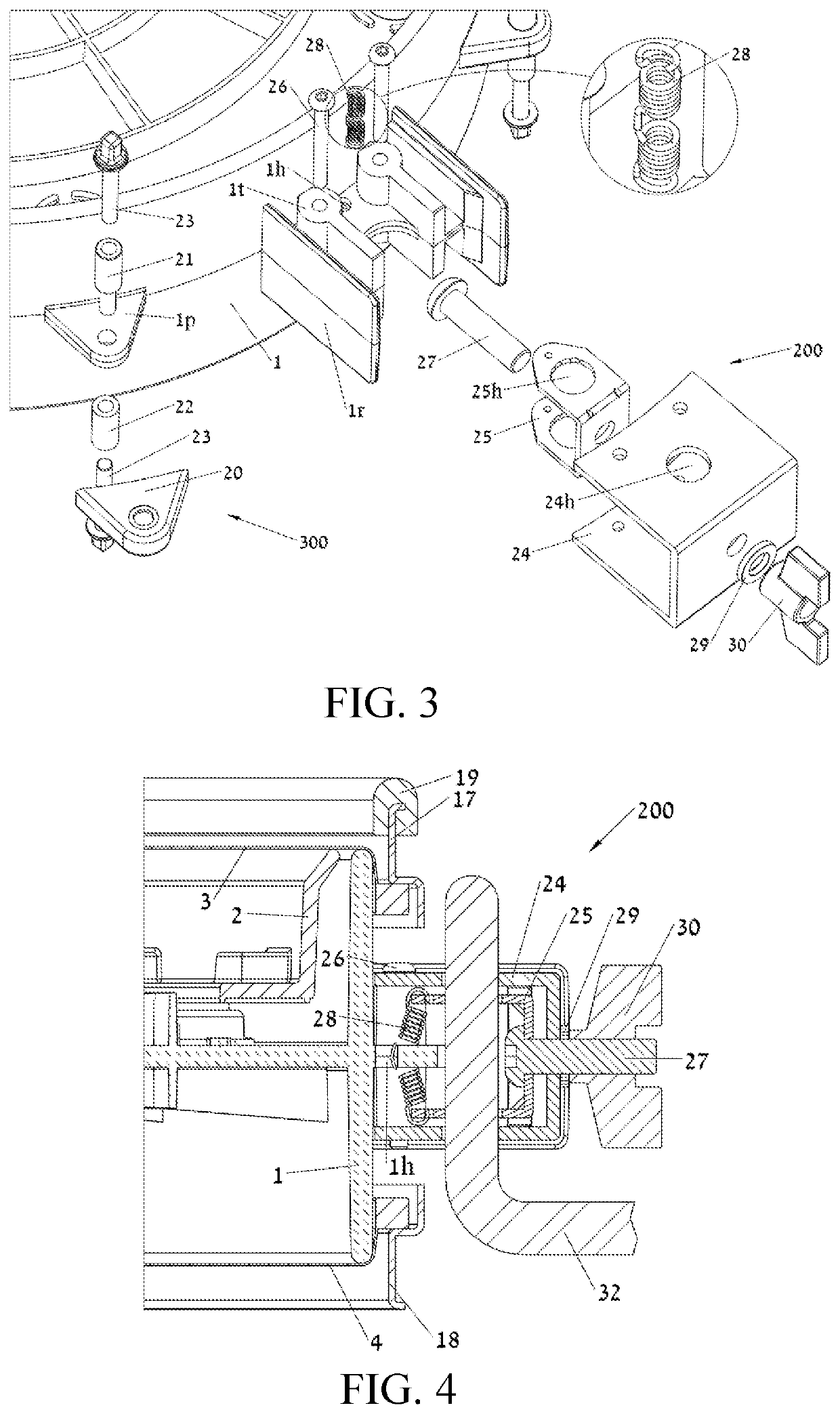
[0030]FIG. 1 is a perspective view and FIG. 2A is a cross-sectional view of an electronic percussion instrument 100 according to the first embodiment of the invention. A body 1, typically made of plastic, has a structure serving multiple purposes that aid the manufacturing process, saving time and cost. Firstly, the body 1 has two ends where a top drumhead 3 and a bottom drumhead 4 are stretched over, thus the body serves also as a drum shell without requiring manufacturing a separate shell. A top rim 17 extends over and presses against the outer periphery of the top drumhead 3, so that the drumhead 3 is normally kept in a tensioned state and thus able to receive a percussion strike induced by a user of the instrument. In a similar fashion, a bottom rim 18 extends over and presses against the outer periphery of the bottom drumhea...


PUM


Abstract

An electronic percussion instrument includes a body having a top opening and an internal support area, and a drumhead having a striking surface and a drumhead bottom surface opposite thereto, the drumhead is stretched over the top opening of the body and is configured to receive a percussion strike thereon, and at least one peripheral sensor disposed on the internal support area of the body, and at least one rising element configured to be flexible and disposed on the internal support area of the body, and a peripheral carrier, adapted to receiving vibrations from the periphery of the drumhead, the peripheral carrier is supported by the at least one rising element such that a pressing force is formed for setting a top circumferential edge of the peripheral carrier in contact with the drumhead bottom surface.

Description

CROSS-REFERENCE TO RELATED APPLICATIONS[0001]This application claims the benefit of U.S. Provisional Application No. 62 / 833980, filed Apr. 15, 2019.BACKGROUND OF THE INVENTION1. Field of the Invention[0002]This invention relates to electronic percussion instruments such as electronic drums and cymbals, and more specifically to electronic percussion instruments that faithfully detect the location of an impinging percussion stroke and have an improved design for manufacturing.2. Description of Related Art[0003]Generally, electronic percussion instruments include a drumhead, typically a mesh type, which is stretched over a shell, a generally tubular body, using a metallic rim extending over the circumference of a drumhead and fastened to the shell using the so called lugs attached to the shell. A generally bowl shaped part is disposed in the interior of the shell, to allow for mounting of sensors, typically piezoelectric type, for conversion vibration energy induced by a percussion str...

Claims


Application Information

Patent Timeline
IPC IPC(8): G10H3/14G10H1/06G10H1/32G10D13/02
CPCG10H3/143G10D13/02G10H2220/531G10H1/06G10H3/146G10H1/32G10D13/26G10H2230/301G10H2230/285
Inventor SHEMESH, GUY
Owner SHEMESH GUY
Learn More