
Imaging Systems and Related Methods Including Radar Imaging with Moving Arrays or Moving Targets

a radar imaging and moving target technology, applied in the field of imaging systems, can solve the problems of limited passenger throughput and substantial system footprin

Pending Publication Date: 2020-10-08
BATTELLE MEMORIAL INST
View PDF34 Cites 15 Cited by
  • Summary
  • Abstract
  • Description
  • Claims
  • Application Information

AI Technical Summary

Benefits of technology

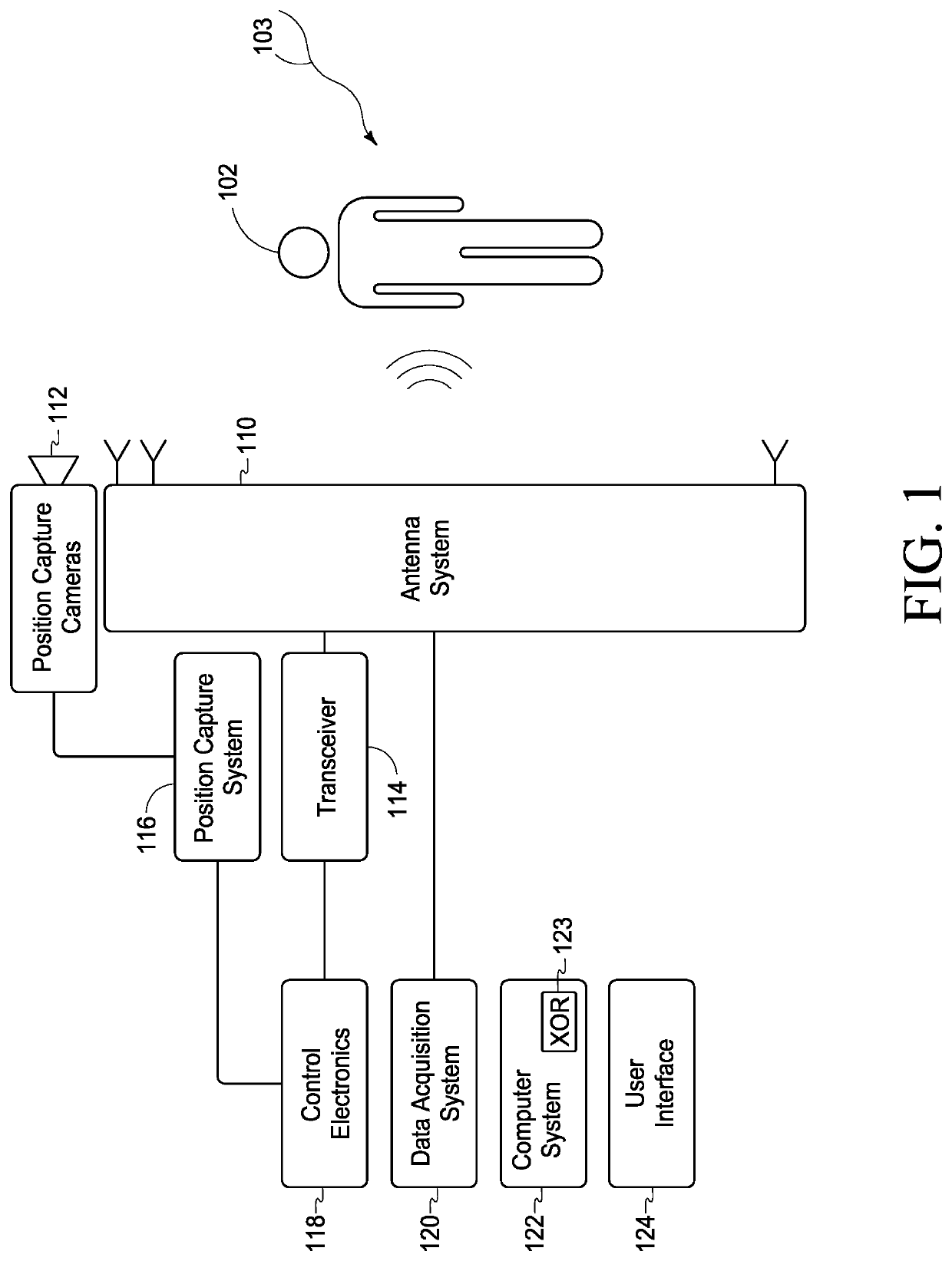
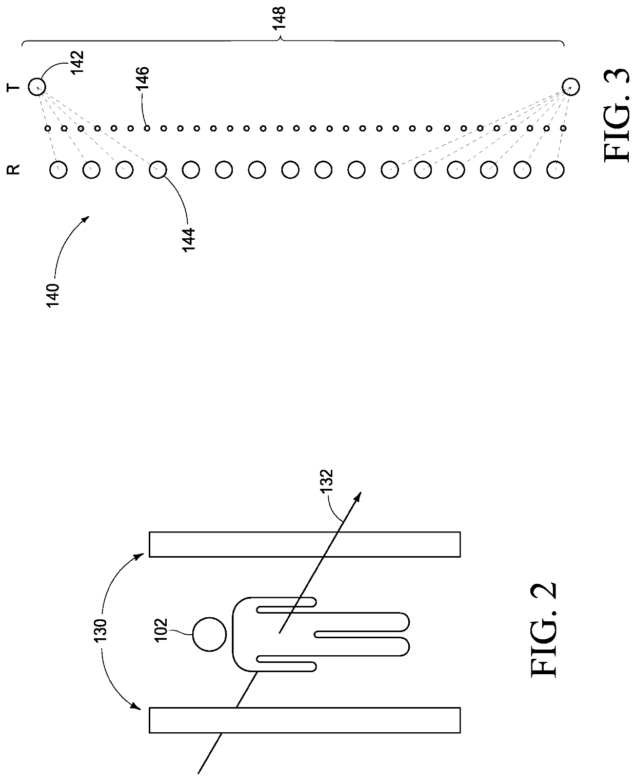
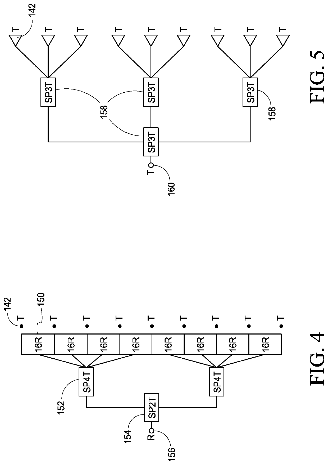
The patent is about a system for high-resolution imaging of moving targets using microwave technology. The system uses a non-uniform scanning aperture or complex target motion to improve screening throughput and passenger convenience. The system includes an antenna array with columns of antennas and a signal distribution switching manifold for efficient imaging. The patent also describes a position capture system and an imaging system for 3D imaging of a moving target in front of a fixed multistatic array. The technical effects of the patent include improved screening efficiency, improved passenger convenience, and improved imaging quality.

Problems solved by technology

Although the currently fielded systems are highly versatile, limitations include requiring the passenger to assume a defined pose during the screening process, limited passenger throughput, and substantial system footprint.

Method used


Image

  • Imaging Systems and Related Methods Including Radar Imaging with Moving Arrays or Moving Targets
  • Imaging Systems and Related Methods Including Radar Imaging with Moving Arrays or Moving Targets
  • Imaging Systems and Related Methods Including Radar Imaging with Moving Arrays or Moving Targets

Examples


Embodiment Construction

[0026]This disclosure is submitted in furtherance of the constitutional purposes of the U.S. Patent Laws “to promote the progress of science and useful arts” (Article 1, Section 8).

[0027]The reader is directed to the following US utility applications which were filed the same day as the present application: “Imaging Systems and Related Methods Including Radar Imaging with Moving Arrays or Moving Targets”, naming David M. Sheen, Richard Trevor Clark, Jonathan R. Tedeschi, A. Mark Jones and Thomas E. Hall as inventors, and having attorney docket number 31358-E (BA4-0730); and “Imaging Systems and Related Methods Including Radar Imaging with Moving Arrays or Moving Targets”, naming David M. Sheen and Richard Trevor Clark as inventors, and having attorney docket number 31371-E (BA4-0784), and the teachings of each are incorporated herein by reference.

[0028]Some example imaging systems described herein are designed to improve passenger convenience and screening throughput by allowing a p...


PUM


Abstract

Imaging systems, including radio frequency, microwave and millimeter-wave arrangements, and related methods are described. According to one aspect, an imaging system includes an antenna array, a position capture system configured to generate position information indicative of locations of one of the antenna array and the target at the first and second moments in time, and wherein the one of the antenna array and the target move between the first and second moments in time, a transceiver configured to control the antenna array to emit electromagnetic energy towards the target and to generate an output that is indicative of the received electromagnetic energy, a data acquisition system configured to generate radar data, processing circuitry configured to process the position information and the radar data to generate image data regarding the target, and an interface configured to use the image data to generate visual images regarding the target.

Description

RELATED PATENT DATA[0001]This application claims the benefit of U.S. Provisional Patent Application Ser. No. 62 / 829,531, filed Apr. 4, 2019, titled “High-Resolution 3D Microwave Imaging of a Moving Target using Optical Motion Capture”, the disclosure of which is incorporated herein by reference.STATEMENT AS TO RIGHTS TO INVENTIONS MADE UNDER FEDERALLY-SPONSORED RESEARCH AND DEVELOPMENT[0002]This invention was made with Government support under Contract DE-AC0576RL01830 awarded by the U.S. Department of Energy. The Government has certain rights in the invention.TECHNICAL FIELD[0003]This disclosure relates to imaging systems, including radio frequency (RF), microwave and millimeter-wave systems, and related methods.BACKGROUND OF THE DISCLOSURE[0004]Systems have been utilized to enhance security at numerous public venues, including airports, public arenas, courthouses, etc. These systems have been primarily directed towards detecting objects, such as weapons, explosives, etc. which are...

Claims


Application Information

Patent Timeline
Patent Type & Authority Applications(United States)
IPC IPC(8): G01S13/90G01S7/35G01S13/42H04N23/90
CPCG01S13/90G01S2007/356G01S13/426G01S7/352G01S13/89G01S2013/0245G01S13/867G06T7/292G06T7/70G01S7/354G01S13/34G06F3/04815G06T2207/10044G06T2207/30208G01S7/2955G01S7/356H04N23/90
Inventor SHEEN, DAVID M.CLARK, RICHARD TREVORTEDESCHI, JONATHAN R.JONES, A. MARKHALL, THOMAS E.
Owner BATTELLE MEMORIAL INST
Learn More