Pipeline valve for closing and/or switching
a technology for water valves and pipes, applied in the direction of valve housings, valve operating means/release devices, mechanical equipment, etc., can solve the problems of reducing utility, desirability and operation efficiency, and requiring significant force, and achieve the effect of convenient adjustmen
- Summary
- Abstract
- Description
- Claims
- Application Information
AI Technical Summary
Benefits of technology
Problems solved by technology
Method used
Image

Examples
first embodiment
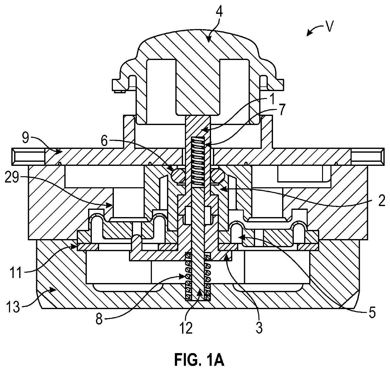
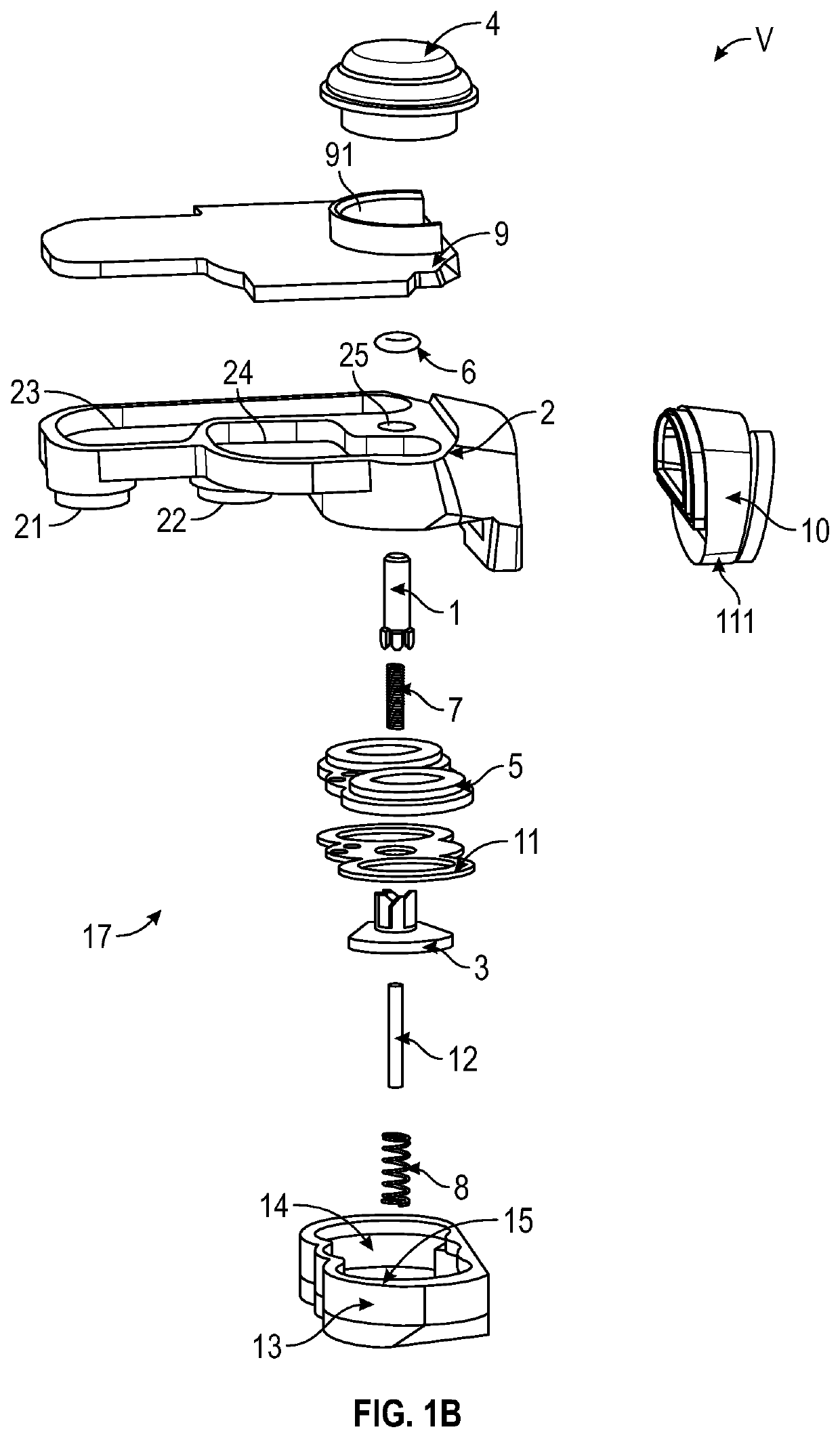
[0059]FIGS. 1-11 show a pipeline valve V that can be easily operated to adjust, including closing and / or switching, the flow of water through the valve by a person. As shown in FIGS. 1A and B the pipeline valve V generally includes a valve body, an inlet, an outlet, a water stopping member 5, and a switching assembly 17. In this embodiment, the valve body assembly includes a water dividing plate (or an upper valve body) 9, a switching body 2 (or a lower valve body), a water sealing plate 11, a water sealing cover (or a lower cover body) 13, and a water inflow body 10 which are fitted to each other or assembled together to form the valve V. As discussed below, the pipeline valve V includes an actuator (e.g., button 4) that an operator or person can efficiently and accurately actuate to change the water discharge flow path of the valve V. The pipeline valve V can be implemented with a showerhead where one of the valve's discharge outlets can discharge massage or jet-style water with g...
second embodiment
[0083]FIGS. 9-21 show the pipeline valve V2 for closing and / or switching according to an embodiment of the present disclosure includes a valve body, an inlet, an outlet, a water stopping member, a plugging assembly 19 and a switching assembly 17. In this example, the valve body assembly includes an upper cover body 21′, an upper valve body 215 and a lower valve body 25′ which are fitted to each other. In one example, the upper valve body 215 and the lower valve body 25′ are connected by a fixing member, for example, a bolt 214.
[0084]Referring to FIGS. 10 and 11, a right end of the lower valve body 25′ is provided as an inlet 251. Correspondingly, a first outlet 252 and a second outlet 253 are sequentially provided at a left end of the lower valve body 25′, and the first outlet 252 and the second outlet 253 are respectively communicated with a water receiving chamber (to be described in detail below) of the valve body. It should be noted that, in this example, one inlet and two outle...
PUM
 Abstract
Description
Claims
Application Information
 - R&D
- Intellectual Property
- Life Sciences
- Materials
- Tech Scout
- Unparalleled Data Quality
- Higher Quality Content
- 60% Fewer Hallucinations
Browse by: Latest US Patents, China's latest patents, Technical Efficacy Thesaurus, Application Domain, Technology Topic, Popular Technical Reports.
© 2025 PatSnap. All rights reserved.Legal|Privacy policy|Modern Slavery Act Transparency Statement|Sitemap|About US| Contact US: help@patsnap.com