Ir illumination module for mems-based eye tracking

a technology of illumination module and eye tracking, which is applied in the direction of acquiring/recognizing eyes, instruments, optical elements, etc., can solve the problem that users often express feelings of discomfor

Active Publication Date: 2020-09-10
MICROSOFT TECH LICENSING LLC
View PDF0 Cites 3 Cited by
  • Summary
  • Abstract
  • Description
  • Claims
  • Application Information

AI Technical Summary

Benefits of technology

[0008]In some embodiments, iris recognition illumination systems utilize an (RGB) laser device that is associated with a first collimating optic and that generates RGB laser light. The system also includes an IR illumination device that is associated with a second collimating optic and that generates IR light. The IR illumination device is positioned at a fixed position relative to the RGB laser device. In some cases, the focal length of the IR light is different than the focal length of the RGB laser light. The system also includes a display module assembly (DMA) that includes a microelectromechanical scanning (MEMS) mirror system. The DMA optically combines the IR light with the RGB laser light to generate combined light. This combined light is directed towards a user's iris via a transport medium (e.g., a waveguide). One or more (e.g., or a plurality such as an array of) photodetector(s) are configured to capture reflected light that is reflected off of the user's eye / iris as a result of the combined light being directed towards the user's iris via the transport medium (e.g., the waveguide). The photodetectors include at least an IR detector configured to detect reflected IR light included as a part of the reflected light. This reflected IR light is used by the iris recognition system to perform iris recognition.
[0009]This Summary is provided to introduce a selection of concepts in a simplified form that are further described below in the Detailed Description. This Summary is not intended to identify key features or essential features of the claimed subject matter, nor is it intended to be used as an aid in determining the scope of the claimed subject matter.

Problems solved by technology

Unfortunately, users often express feelings of discomfort as a result of these somewhat bulky cameras being positioned so near their eyes.

Method used


Image

  • Ir illumination module for mems-based eye tracking
  • Ir illumination module for mems-based eye tracking
  • Ir illumination module for mems-based eye tracking

Examples


Embodiment Construction

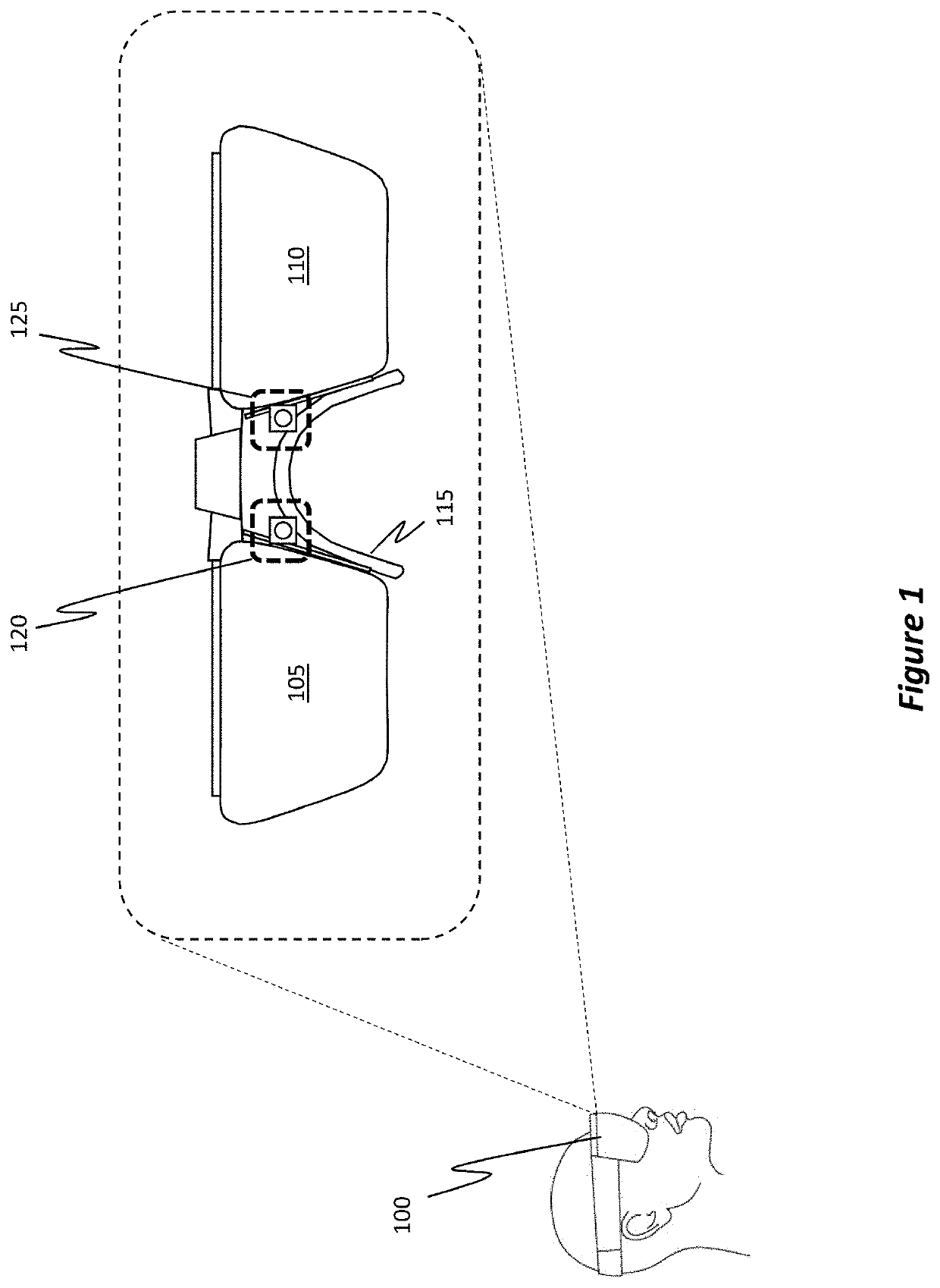
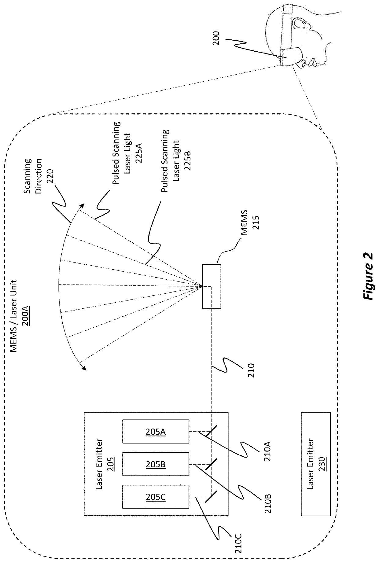
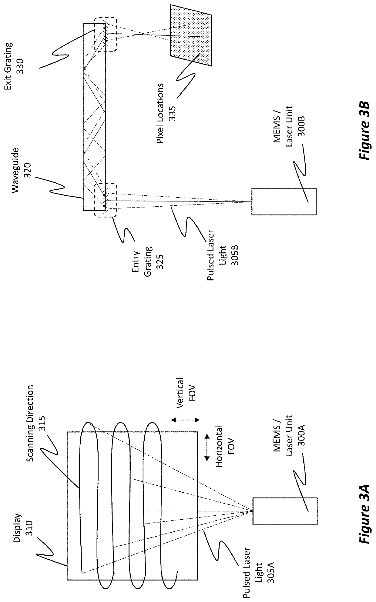
[0026]Disclosed embodiments include iris recognition illumination systems and methods of use, where the iris recognition illumination systems utilize IR (infrared) light to perform the iris recognition. The IR illumination systems generate IR light that is passed through an integrated scanning waveguide display with red, green, blue (RGB) light. The reflected IR light is sensed with an IR sensor to perform iris detection. In some instances, the system is capable of performing iris recognition without requiring the use of separate iris detection cameras or illumination devices.

[0027]In some embodiments, an iris recognition illumination system includes an RGB laser device and a first collimating optic. The system also includes an IR illumination device and a second collimating optic. In some cases, the focal length of the IR light is different than the focal length of the RGB laser light. The system also includes a display module assembly (DMA) that includes a microelectromechanical s...


PUM

PropertyMeasurementUnit
focal lengthaaaaaaaaaa
beam sizeaaaaaaaaaa
beam sizeaaaaaaaaaa

Abstract

An improved iris recognition illumination system is disclosed. The system includes (i) an RGB laser device that is associated with a first collimating optic and (ii) an IR illumination device that is associated with a second collimating optic. The system also includes a DMA that has a MEMS mirror system. The DMA optically combines IR light and RGB light to generate combined light. The combined light is then directed towards a user's iris via a transport medium (e.g., a waveguide). One or more photodetector(s) are positioned to capture reflected light that is reflected off of the user's iris. The photodetectors include an IR detector configured to detect reflected IR light off of the user's iris in order to perform iris recognition.

Description

BACKGROUND[0001]Mixed-reality systems, including virtual-reality (VR) and augmented-reality (AR) systems, have received significant attention because of their ability to create truly unique experiences for their users. For reference, conventional VR systems create a completely immersive experience by restricting their users' views to only virtual environments. This is often achieved through the use of a head-mounted device (HMD) that completely blocks any view of the real world. As a result, a user is entirely immersed within the virtual environment. In contrast, conventional AR systems create an augmented-reality experience by visually presenting virtual images (i.e. “holograms”) that are placed in or that interact with the real world.[0002]As used herein, VR and AR systems are described and referenced interchangeably. Unless stated otherwise, the descriptions herein apply equally to all types of mixed-reality systems, which (as detailed above) include AR systems, VR systems, and / o...

Claims


Application Information

Patent Timeline
Patent Type & Authority Applications(United States)
IPC IPC(8): G06K9/00G06F3/01G02B26/08G02B27/01G02B27/00G02B27/30G02B26/10G06V10/143G06V10/147
CPCG06K9/00604G02B2027/0174G02B27/0172G02B2027/0178G02B26/101G06K9/0061G02B2027/0138G02B26/0833G02B2027/014G06F3/013G02B27/30G02B27/0093G02B5/00G02B26/105G02B27/1006G06V40/18G06V10/143G06V10/147G06V40/19G06V40/193
Inventor PRICE, RAYMOND KIRKPOON, YARN CHEEULANCH, RACHEL N.YEE, RASHELLE KAY
Owner MICROSOFT TECH LICENSING LLC
Why Eureka
Try Eureka