
Air conditioning system

a technology of air conditioning system and fan coil unit, which is applied in the field of air conditioning system, can solve the problems of difficult to determine the temperature change, difficult to apply the prior art technique to the fan coil unit, etc., to achieve the effect of shortening the time required for searching, facilitating the cooling and heating of the room, and facilitating installation

Active Publication Date: 2020-08-20
LG ELECTRONICS INC
View PDF3 Cites 0 Cited by
  • Summary
  • Abstract
  • Description
  • Claims
  • Application Information

AI Technical Summary

Benefits of technology

This patent describes a method for quickly and efficiently finding and controlling the heating and cooling pipes connected to each fan coil unit in an air conditioning system. The search for the pipes is done in parallel with the heating and cooling operations, which saves time. The system can also control the flow of each fan coil unit at the optimal set point, resulting in quicker cooling and heating of the room and improved overall efficiency of the air conditioning system. Additionally, the search time for each pipe search is measured, eliminating the need for a separate time measurement for optimizing the set point.

Problems solved by technology

On the other hand, the simultaneous cooling and heating type multi air conditioner is provided with a distributor between the outdoor unit and the indoor unit to adjust refrigerant supplied to the indoor unit to allow the indoor unit to operate the cooling and heating operation, and when the pipe connection state of the distributor and a plurality of indoor devices are incorrect, there is a malfunction problem that the indoor unit which should operate cooling operation may perform the heating operation is performed or a malfunction problem may be caused, another indoor device operates, or the like.
However, unlike the refrigerant distributor, since the fan coil unit uses a water channel, it is difficult to determine a temperature change when hot water and cold water are mixed in the water channel, and it is difficult to apply the technique of the prior art to the fan coil unit.
However, since the heat exchanger and the fan coil unit in the distributor use a closed channel and all the fan coil units are connected to the distributor, it is difficult to apply the technique of the prior art to the fan coil unit.

Method used


Image

  • Air conditioning system
  • Air conditioning system
  • Air conditioning system

Examples


Embodiment Construction

[0031]Hereinafter, specific embodiments of the present disclosure will be described in detail with reference to the drawings.

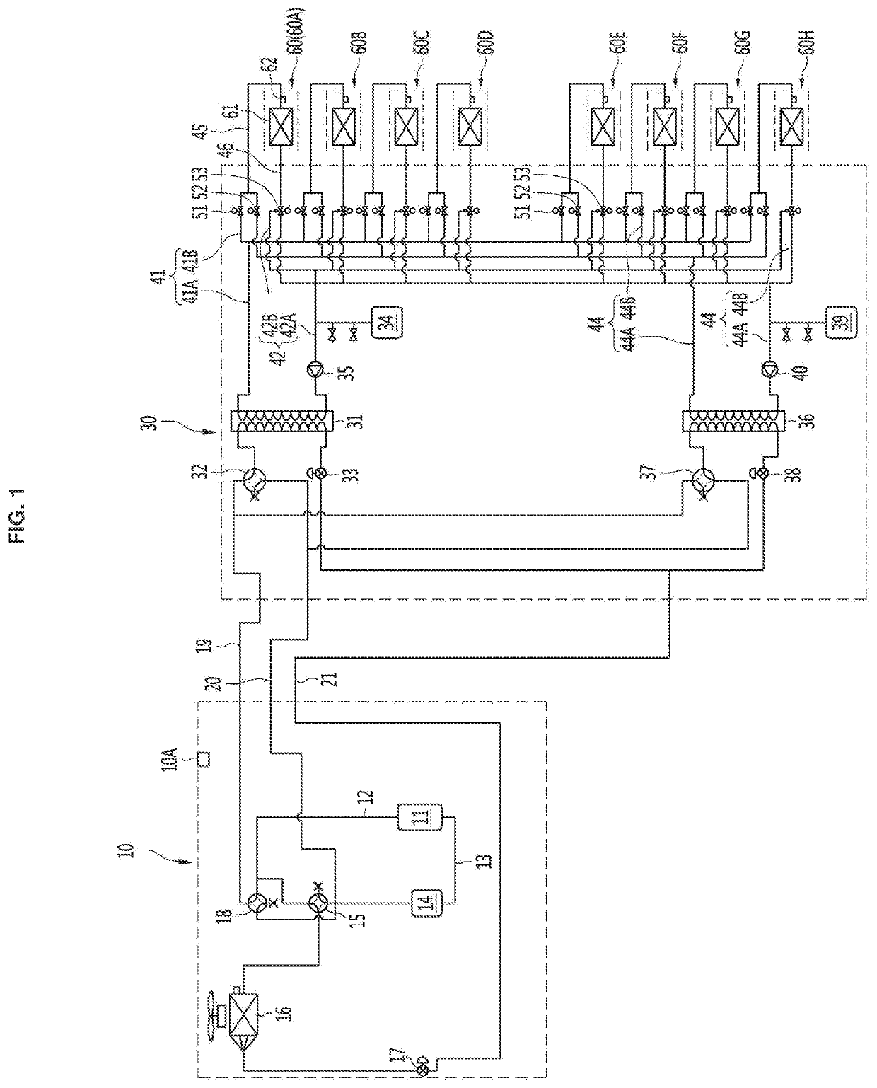
[0032]FIG. 1 is a schematic configuration diagram of an air conditioning system according to an embodiment of the present disclosure.

[0033]An air conditioning system according to an embodiment of the present disclosure may be a switchable or simultaneous type air conditioner.

[0034]The air conditioning system may include an outdoor unit 10, at least one distributor 30 connected to the outdoor unit 10, and a plurality of fan coil units 60 connected to the distributor 30.

[0035]The air conditioning system may control the outdoor unit 10 with a cooling-oriented operation or a heating-oriented operation according to a cooling load and a heating load required by the plurality of fan coil units 60. Of course, the air conditioning system is capable of performing an all-indoor unit cooling operation or an all-indoor unit heating operation.

[0036]The outdoor unit 10 may b...


PUM


Abstract

An air conditioning system according to an embodiment may include an outdoor unit including a compressor; at least one distributor connected to the outdoor unit and including a condenser and an evaporator that exchange heat between a refrigerant and water with each other; a plurality of heating pipes in communication with the condenser; a plurality of cooling pipes in communication with the evaporator; a plurality of fan coil units connected to the heating pipes or the cooling pipes; and a controller configured to perform a heating pipe search operation for matching a portion of the plurality of fan coil units with the plurality of heating pipes, and a cooling pipe search operation for matching another portion of the plurality of fan coil units with the plurality of cooling pipes, in parallel.

Description

TECHNICAL FIELD[0001]The present disclosure relates to an air conditioning system, and more particularly, to an air conditioning system including a fan coil unit.BACKGROUND ART[0002]In general, an air conditioner is a device for cooling or heating an indoor space such as a living space, a restaurant, an office or the like. To efficiently cool or heat an indoor space which is divided into a plurality of rooms, a simultaneous cooling and heating type multi air conditioner capable of cooling or heating each room has been continuously developed.[0003]In particular, a fan coil unit (FCU) receives cold water or hot water from a freezer or a boiler during cooling and heating of a building, cools or heats surrounding air by allowing the cold or hot water to pass through a heat exchanger, and then discharge heat-exchanged air to a room according to the driving of a blower to achieve cooling and heating.[0004]On the other hand, the simultaneous cooling and heating type multi air conditioner i...

Claims


Application Information

Patent Timeline
IPC IPC(8): F24F11/30F24F11/63
CPCF25B2600/2513F24F11/63F24F11/30F25B13/00F24F2140/20F24F2110/10F24F11/49F25B2313/003F25B2313/007F25B2313/0231F25B2313/0233F25B2313/02732F25B2700/2106F24F1/32F25B2700/2103F25B2500/26F24F1/00077F25B2600/01F24F11/67F25B2600/2515F24F11/84
Inventor SHIN, YOUNGJOOLEE, JAEWONSHIN, ILYOONG
Owner LG ELECTRONICS INC
Learn More