
Camera, method, non-transitory computer-readable medium, and system

a computer-readable medium and camera technology, applied in the field of information processing apparatus, information processing method, program, etc., can solve the problem of not being able to record the setting state at that tim

Active Publication Date: 2020-08-06
SONY CORP
View PDF0 Cites 2 Cited by
  • Summary
  • Abstract
  • Description
  • Claims
  • Application Information

AI Technical Summary

Benefits of technology

The technical effect of this patent is that it allows for accurate reproduction of data even if there were errors during transmission or storage.

Problems solved by technology

The technical problem addressed by this patent is how to ensure that settings stored in a camera's RAM are retained even if power interruption occurs during use.

Method used


Image

  • Camera, method, non-transitory computer-readable medium, and system
  • Camera, method, non-transitory computer-readable medium, and system
  • Camera, method, non-transitory computer-readable medium, and system

Examples


application example

4. Application Example

[0129]The technology according to the present disclosure is applicable to a variety of products. For example, the technology according to the present disclosure may be realized as an apparatus mounted to any one kind of moving body such as automobile, electric vehicle, hybrid electric vehicle, motorcycle, bicycle, personal mobility, airplane, drone, ship, robot, construction machinery, and agricultural machinery (tractor).

[0130]FIG. 14 is a block diagram illustrating an example of a schematic configuration of a vehicle control system 7000, an example of a mobile body control system to which the technology according to the present disclosure is applicable. The vehicle control system 7000 includes a plurality of electronic control units connected to each other via a communication network 7010. In the example illustrated in FIG. 14, the vehicle control system 7000 includes a driving system control unit 7100, a body system control unit 7200, a battery control unit ...


PUM


Abstract

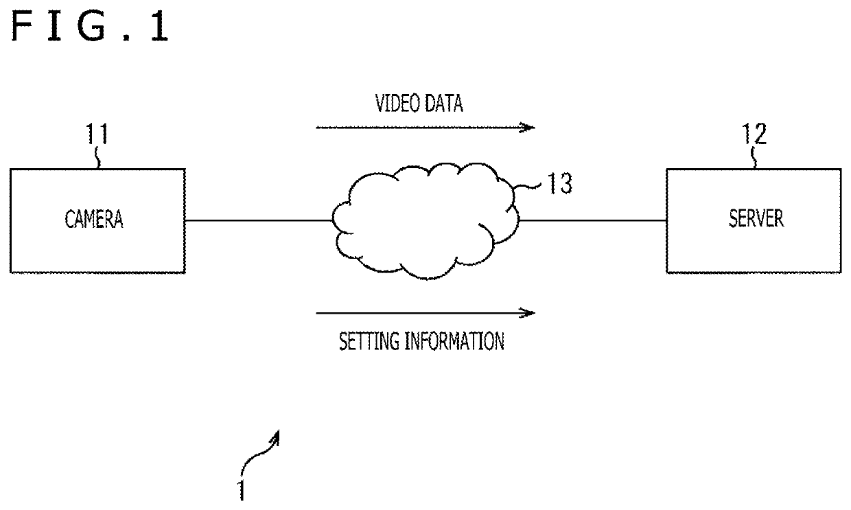
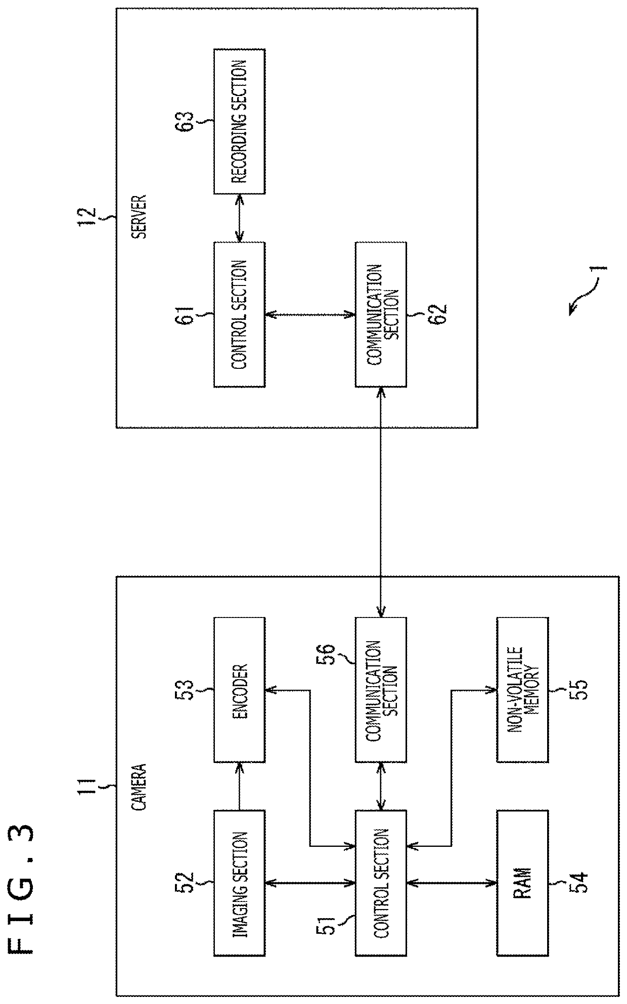
The present disclosure includes an information processing apparatus, an information processing method, a non-transitory computer-readable medium, and a system. In one example, the information processing apparatus is a camera. The camera includes a memory, communication circuitry, and control circuitry. The memory is configured to store a first set of backup camera settings. The communication circuitry is configured to communicate with a server, the server configured to store a second set of backup camera settings. The control circuitry is configured to perform a start-up process when the camera is turned ON, the start-up process includes comparing the first set of backup camera settings to the second set of backup camera settings to determine whether the first set of backup camera settings is newer than the second set of backup camera settings.

Description


Claims


Application Information

Patent Timeline
Owner SONY CORP
Learn More