Motion state evaluation system, motion state evaluation device, motion state evaluation server, motion state evaluation method, and motion state evaluation program
a technology of motion state and evaluation system, applied in the field of motion form analysis system, can solve the problems of preventing an individual from easily conducting analysis and not being able to conduct accurate analysis
- Summary
- Abstract
- Description
- Claims
- Application Information
AI Technical Summary
Benefits of technology
Problems solved by technology
Method used
Image

Examples
first embodiment
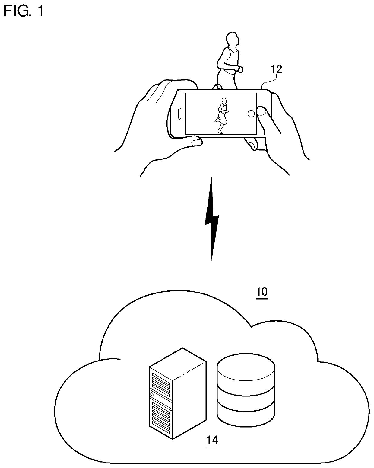
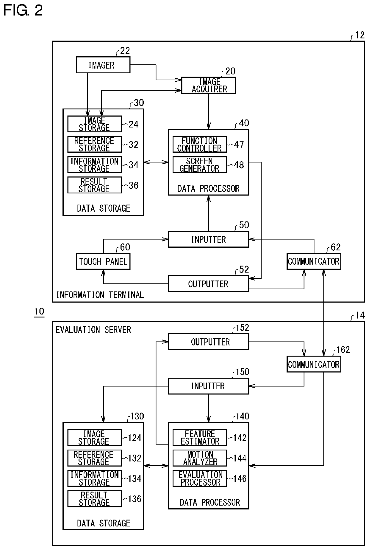
[0041]FIG. 1 schematically shows a structure of a motion state evaluation system 10. The motion state evaluation system 10 includes an information terminal 12 and an evaluation server 14, and the information terminal 12 and the evaluation server 14 cooperate together to make various functions implemented in the motion state evaluation system 10 work. According to the present embodiment, the information terminal 12 is responsible for acquiring a moving image of a subject and displaying a result of evaluation of motion on a screen, and the evaluation server 14 is responsible for analyzing the moving image and conducting the evaluation. The moving image of the subject acquired by the information terminal 12 is transferred to the evaluation server 14 over a communication means such as radio communication, and the evaluation server 14 analyzes the moving image and conducts the evaluation. The evaluation result is transferred to the information terminal 12 and displayed on the screen of t...
second embodiment
[0082]FIG. 12 is a functional block diagram showing basic structures of the information terminal 12 and an analysis server 16 according to a second embodiment. A motion state evaluation system 10 according to the present embodiment is different from the motion state evaluation system 10 according to the first embodiment in that the motion state evaluation system 10 according to the present embodiment includes the information terminal 12 and the analysis server 16, and the “evaluation processor” is provided in the information terminal 12 rather than in a server (analysis server 16). Hereinafter, a description will be given mainly of differences from the first embodiment, and no description will be given of common points.
[0083]The analysis values P of the various running form parameters analyzed by the motion analyzer 144 are transmitted to the information terminal 12 by the outputter 152 and the communicator 162. The reference storage 32 of the information terminal 12 stores a regres...
third embodiment
[0086]FIG. 14 is a functional block diagram showing basic structures of an information terminal 12 and an analysis server 16 according to a third embodiment. A motion state evaluation system 10 according to the present embodiment is different from the motion state evaluation system 10 according to the first embodiment in that the motion state evaluation system 10 according to the present embodiment includes the information terminal 12 and the analysis server 16, and the “motion analyzer” and the “evaluation processor” are provided in the information terminal 12 rather than in a server (analysis server 16). Further, the motion state evaluation system 10 according to the present embodiment is different from the motion state evaluation system 10 according to the second embodiment in that the “motion analyzer” is provided in the information terminal 12 rather than in the server (analysis server 16). Hereinafter, a description will be given mainly of differences from the first embodiment...
PUM
 Abstract
Description
Claims
Application Information
 - Generate Ideas
- Intellectual Property
- Life Sciences
- Materials
- Tech Scout
- Unparalleled Data Quality
- Higher Quality Content
- 60% Fewer Hallucinations
Browse by: Latest US Patents, China's latest patents, Technical Efficacy Thesaurus, Application Domain, Technology Topic, Popular Technical Reports.
© 2025 PatSnap. All rights reserved.Legal|Privacy policy|Modern Slavery Act Transparency Statement|Sitemap|About US| Contact US: help@patsnap.com