
Humidifying device and corrugating machine

a technology of humidifying device and corrugating machine, which is applied in the direction of mechanical working/deformation, ceramic shaping apparatus, coatings, etc., can solve the problems of decreasing the moisture content of the liner paper reducing the penetration depth, and reducing the moisture content of the surface layer at the same time, so as to achieve the optimum moisture content of the liner paper, suppress the heat dissipation of the liquid held in the chamber, and satisfactory a

Inactive Publication Date: 2020-08-06
MITSUBISHI HEAVY IND MACHINERY SYST LTD
View PDF0 Cites 6 Cited by
  • Summary
  • Abstract
  • Description
  • Claims
  • Application Information

AI Technical Summary

Benefits of technology

The present invention provides a humidifying device for a corrugating machine that prevents heat dissipation and ensures proper humidification of the liner paper. This is achieved by holding the heated liquid for humidification in a highly sealable chamber and supplying it to the liquid application roller via an opening that is smaller than the diameter of the roller. This design allows for optimal holding of heat and moisture, resulting in improved affixing strength of the liner paper. Additionally, the humidifying device is placed downstream of the preheater, ensuring the temperature and moisture content of the liner paper are optimized for optimal affixing performance.

Problems solved by technology

Although the moisture of the liner paper allowing easy glue penetration is 3 to 6 wt % in general, an increase in heating heat amount by the preheater as described above results in a decrease in the moisture of the liner paper (surface layer in particular) at the same time.
The decrease in moisture causes a problem by decreasing the penetration depth as the depth of the glue penetration of the liner paper per unit time.
This, however, leads to a decline in cardboard production efficiency.

Method used


Image

  • Humidifying device and corrugating machine
  • Humidifying device and corrugating machine
  • Humidifying device and corrugating machine

Examples


Embodiment Construction

[0047]Hereinafter, embodiments of the present invention will be described with reference to accompanying drawings.

[0048]Each of the following embodiments is merely an example, and various modifications and technical applications not specified in the following embodiments shall not be excluded. Each configuration of each of the following embodiments can be implemented in various modified forms within the scope of the present invention, can be selected as necessary, or can be appropriately combined.

[0049][1. Configuration of Double Facer and Its Peripheral]

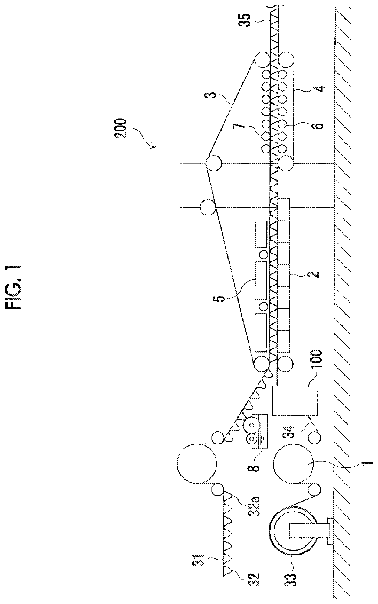
[0050]FIG. 1 is a schematic side view illustrating a double facer of a corrugating machine according to the present embodiment and its neighboring part in an extracted manner. As illustrated in FIG. 1, a double facer 200 manufactures double-faced cardboard 35 by affixing bottom liner paper 34 to single-faced cardboard 31 manufactured with a single facer (not illustrated). Accordingly, the bottom liner paper 34 is affixed to an apex ...


PUM

PropertyMeasurementUnit
temperatureaaaaaaaaaa
shapeaaaaaaaaaa
lengthaaaaaaaaaa

Abstract

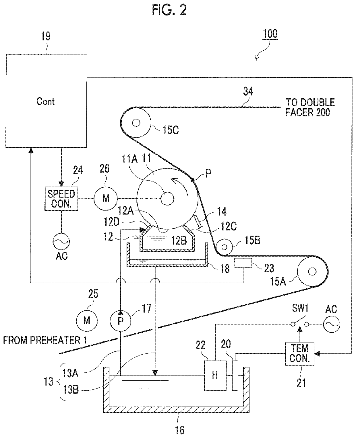
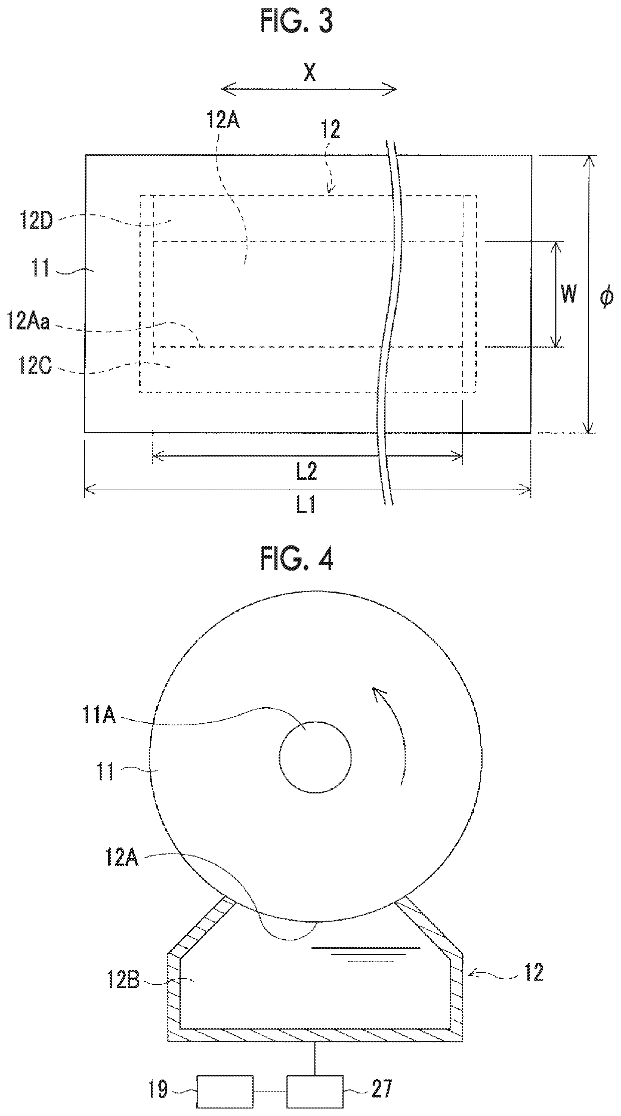
Provided are a humidifying device and a corrugating machine whereby release of heat from heated water is suppressed and a liner paper is humidified. A humidifying device for humidifying a surface liner paper affixed to a core paper via a starch glue has a liquid application roller for applying heated water to the surface liner paper, provided downstream from a preheater for heating the surface liner paper prior to the affixing; and a chamber facing the peripheral face of the liquid application roller and provided with an internal space to which the heated water is supplied. The chamber further has an opening for supplying the heated water to the peripheral face of the liquid application roller, and is formed so that the length of the opening in the direction orthogonal to the axial direction of the liquid application roller is less than the diameter of the liquid application roller.

Description

TECHNICAL FIELD[0001]The present invention relates to a humidifying device humidifying liner paper after heating by a preheater and before affixing to medium paper and a corrugating machine using the humidifying device.BACKGROUND ART[0002]In general, a production line of a cardboard manufacturing apparatus referred to as a corrugating machine is provided with a mill roll stand equipped with rollers for base paper of bottom liner paper, base paper of top liner paper, and base paper of medium base paper that are raw materials of cardboard paper, a splicer as a paper splicing device for continuously supplying cardboard base paper toward the corrugating machine, a single facer forming the medium paper delivered from the mill roll stand into a wave shape and manufacturing single-faced cardboard paper by affixing to the top liner paper via a glue applied to the apex of the wave shape, and a double facer manufacturing double-faced cardboard paper by affixing to the bottom liner paper via a...

Claims


Application Information

Patent Timeline
Patent Type & Authority Applications(United States)
IPC IPC(8): B31F1/28
CPCB31F1/2818B31F1/36B32B2255/12B31F1/2831B31F1/2881B31F1/285B05C1/003B05C1/0813B05C1/0826B31F1/28B31F1/2845B28B19/00
Inventor HARADA, NAOYUKIMIZUTANI, HIDEKI
Owner MITSUBISHI HEAVY IND MACHINERY SYST LTD
Learn More