
Systems and methods for carrier phase recovery

Active Publication Date: 2020-07-23
CABLE TELEVISION LAB
View PDF0 Cites 5 Cited by
  • Summary
  • Abstract
  • Description
  • Claims
  • Application Information

AI Technical Summary

Benefits of technology

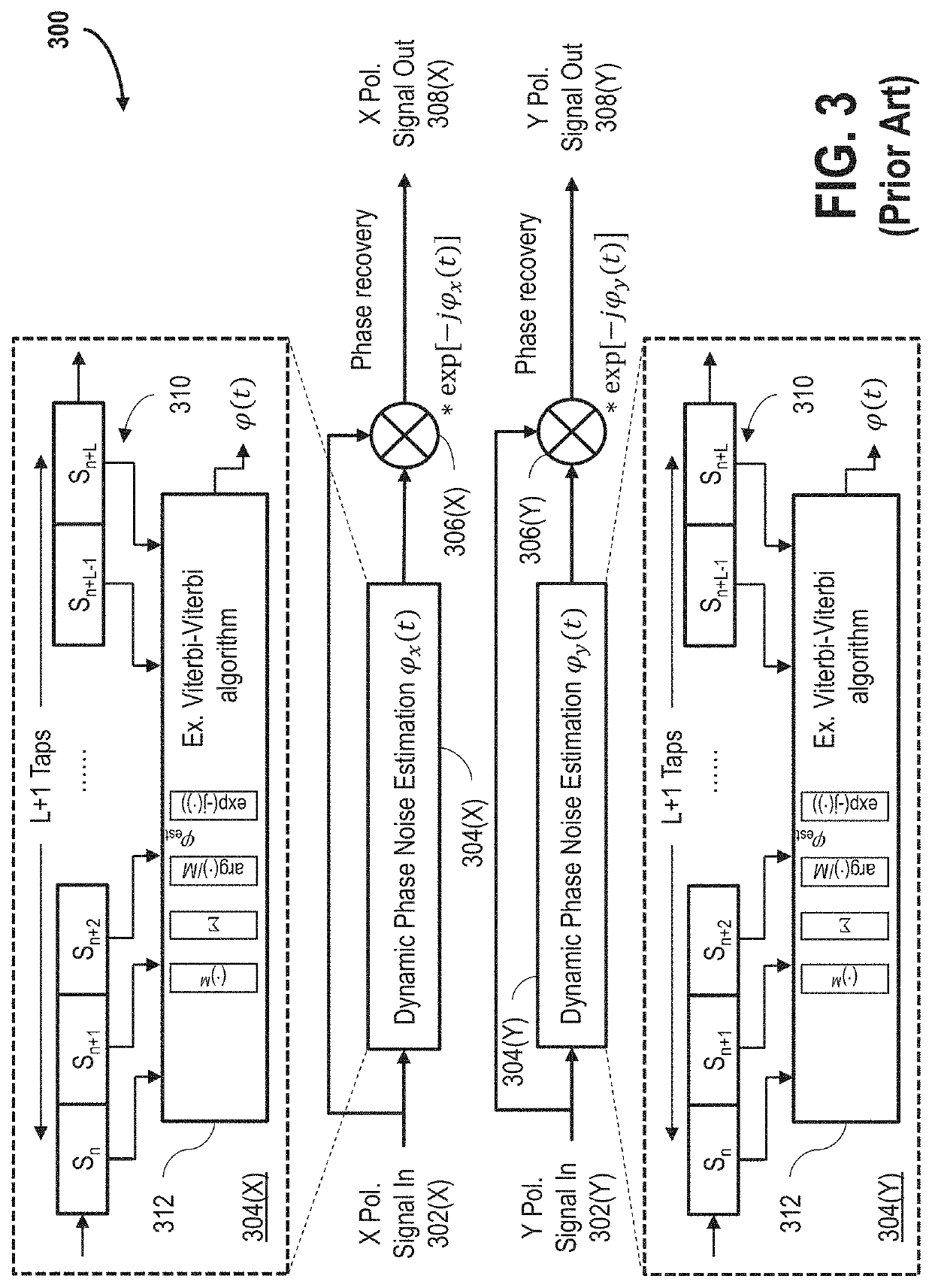
This patent describes a method and apparatus for processing a polarization multiplexed carrier in a communication network. The method includes dynamically estimating phase noise of a first polarization direction, and performing phase recovery for a second polarization direction based on the phase noise estimate. The technical effect is improved carrier phase recovery for a polarization multiplexed carrier, which reduces the effect of phase noise and improves the quality of signal processing.

Problems solved by technology

However, PONs and access optical systems supporting greater than 50 Gb / s per channel have not been conventionally adopted because present direct detection optical schemes do not achieve sufficient power budgets due to their low receiver sensitivity and limited options for long-term upgrading.
These direct detection challenges are particularly prevalent in the legacy fiber environment, where network operators desire the continued use of existing infrastructures to avoid costly fiber re-trenching.
Coherent optics technology is becoming common in the subsea, long-haul, and metro networks, but has not yet been applied to access networks due to the relatively high cost of the technology for such coherent implementations.
This metro solution, however, is nevertheless considered in the field to be over-engineered, and also too expensive, large, and power-demanding to be efficiently and practically implemented in the access paradigm, which is a significantly different environment than the long haul and metro environments.
Nevertheless, conventional DSP techniques and algorithms are unable to meet the size and cost requirements for access applications in developing and future access networks.

Method used


Image

  • Systems and methods for carrier phase recovery
  • Systems and methods for carrier phase recovery
  • Systems and methods for carrier phase recovery

Examples


Embodiment Construction

[0023]In the following specification and claims, reference will be made to a number of terms, which shall be defined to have the following meanings.

[0024]The singular forms “a,”“an,” and “the” include plural references unless the context clearly dictates otherwise.

[0025]“Optional” or “optionally” means that the subsequently described event or circumstance may or may not occur, and that the description includes instances where the event occurs and instances where it does not.

[0026]Approximating language, as used herein throughout the specification and claims, may be applied to modify any quantitative representation that could permissibly vary without resulting in a change in the basic function to which it is related. Accordingly, a value modified by a term or terms, such as “about,”“approximately,” and “substantially,” are not to be limited to the precise value specified. In at least some instances, the approximating language may correspond to the precision of an instrument for measu...


PUM


Abstract

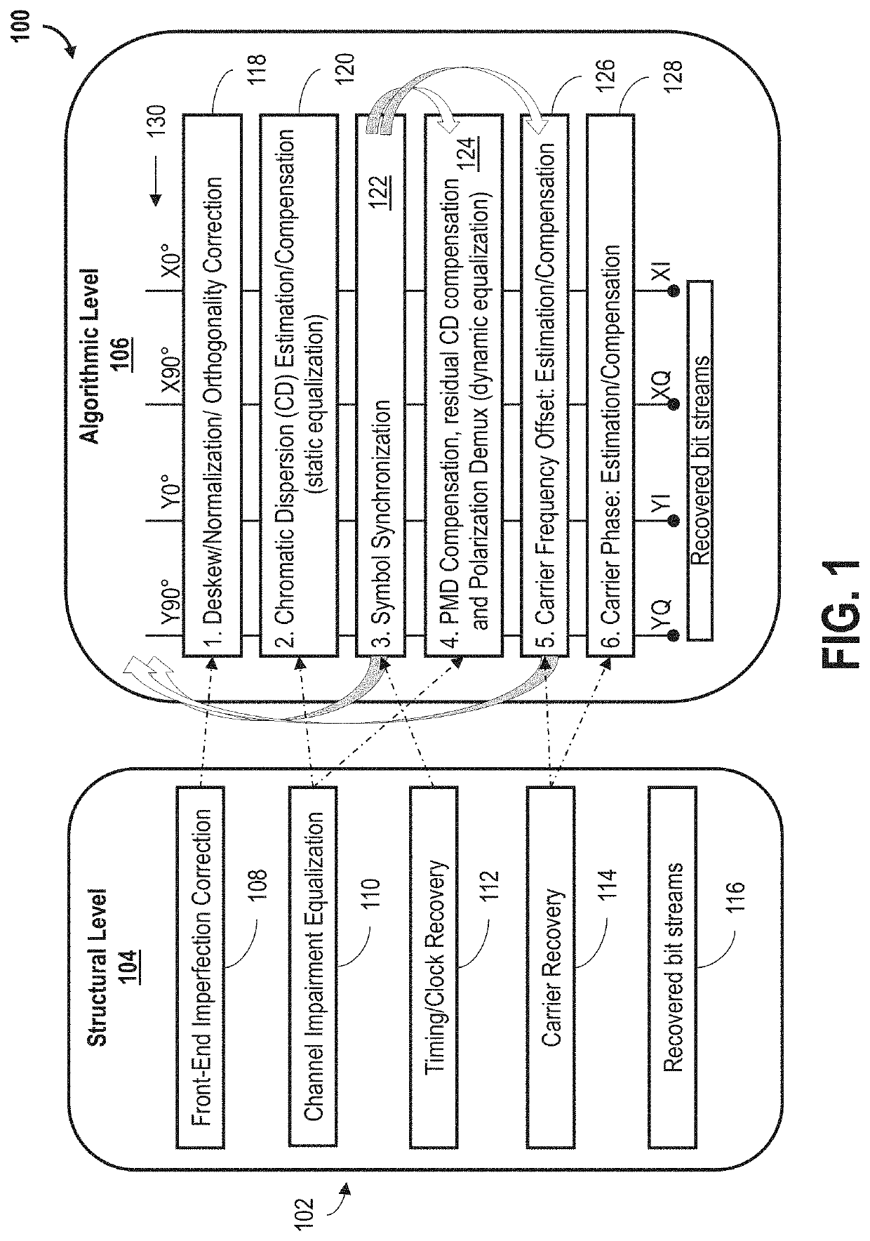
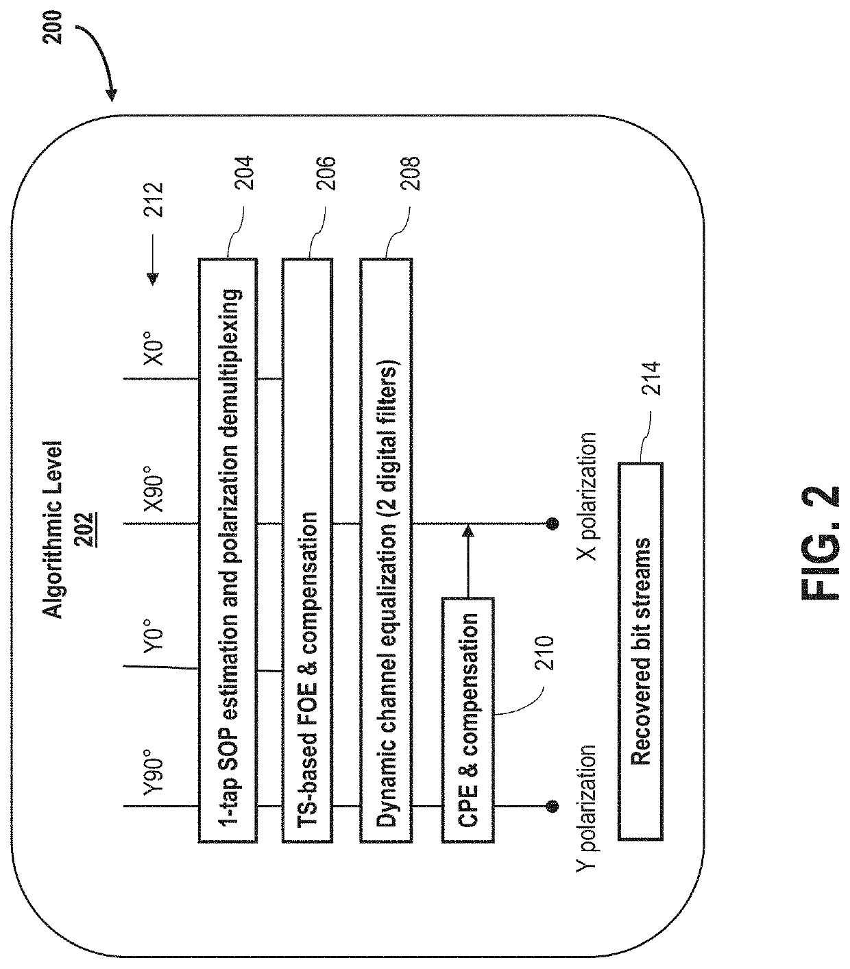
A digital receiver is configured to process a polarization multiplexed carrier from a communication network. The polarization multiplexed carrier includes a first polarization and a second polarization. The receiver includes a first lane for transporting a first input signal of the first polarization, a second lane for transporting a second input signal of the second polarization, a dynamic phase noise estimation unit disposed within the first lane and configured to determine a phase noise estimate of the first input signal, a first carrier phase recovery portion configured to remove carrier phase noise from the first polarization based on a combination of the first input signal and a function of the determined phase noise estimate, and a second carrier phase recovery portion configured to remove carrier phase noise from the second polarization based on a combination of the second input signal and the function of the determined phase noise estimate.

Description

CROSS REFERENCE TO RELATED APPLICATIONS[0001]This application claims the benefit of and priority to U.S. Provisional Patent Application Ser. No. 62 / 790,146, filed Jan. 9, 2019, which is incorporated herein by reference in its entirety.BACKGROUND[0002]The field of the disclosure relates generally to communication networks, and more particularly, to access networks capable of digitally processing carrier signals for point-to-point (P2P) and point-to-multipoint (P2MP) communication systems.[0003]Access networks, driven by ever-increasing residential data service growth rates and numbers of supported services types (e.g., business services, cellular connectivity, etc.), have been undergoing frequent technological and architectural changes. High-speed data and video service bandwidth requirements for the access paradigm are expected to grow to multi-gigabits-per-second (Gb / s) for residential offerings, and over 10-Gb / s for business markets in optical access networks of the near-future. A...

Claims


Application Information

Patent Timeline
IPC IPC(8): H04J14/06H04B10/61
CPCH04J14/06H04B10/677H04B10/612H04B10/6162H04B10/614H04B10/6166H04B10/6165
Inventor JIA, ZHENSHENGZHANG, JUNWENXU, MUZHANG, HAIPENGCAMPOS, LUIS ALBERTOKNITTLE, CURTIS DEAN
Owner CABLE TELEVISION LAB
Learn More